Huge Swing
July 24, 2020
About
Inspired by the Colin Furze 360-swing video, I wanted to try out building a large swing set. I haven't really done any large projects like this before, but I figured I would test out my civil engineering abilities with this structure. Particularly, I wanted to test out the possibility of building this scale swing set by using supporting cables, so that there will be significantly less steel than the Furze design, and significantly less material cost. Of course the swing would have to really make a statement, so the main columns are designed to be 20 ft tall, with the swing section being solid as well and thus capable of going up to 40 ft at peak extension.
Design
In theory, all that is needed for the swing set is two supporting columns, and four anchor points to which cables would run from the top of the columns (two from each) to stabilize them against lateral forces of the swing motion. The bottom of the columns would only need to be kept stable laterally and there would not be a moment load on the columns so there is no requirement for excavation. To improve safety, as I would rely on these cables to keep me from crashing into the ground, I added 6 more cables, for a total of 10 ground anchors and cables, 5 on the top of each column. In addition, I initially thought of using steel for the columns as that was in the Furze design, but on considering material costs and necessary load handling, I concluded that 4x4 wood beams would hold the load, be much cheaper, and be much easier to machine. Thus the swing set consists of large wood columns and steel wire rope supports attached to ground anchors. The use of the ground anchors greatly expands the base area of the structure and its stability, while keeping material consumption to a minimum. Additionally, of the remaining metal components, I modified the design whenever possible to use simple angle sections which are drilled and assembled by hand, removing any need for milling or turning. This was necessary both to simplify my workload and because the covid shutdowns meant all machine shops were closed or inaccessible. The following was the bill of materials:
- Steel angle 2x2x0.125 inch section, 4 inch long 8 pieces, and 12 inch long 4 pieces.
- Steel tube, 1.5 inch OD, 0.25 inch wall thickness, 70 inches long.
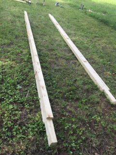
- Wood beams, 4x4 inch, 10 ft, 4 pieces.
- Wood beams, 2x4 inch, 10 ft, 8 pieces.
- Wire rope, 0.125 inch diameter, 500 ft reel.
- Ground anchors, 4 inch diameter auger, 18 inch length, 10 pieces.
- Turnbuckles and wire rope clamps, 10 pieces.
- Bearings, 1.5 inch bore, 2 pieces.
- Big bolts for attaching metal to wood.
- Wood screws for assembling wood structure.
Construction
The current and future economic climate means I won't be owning land any time soon and probably not ever. This places significant limitations on my ability to assemble big projects like this. For this project, I rented a cabin with adjacent cleared land, for 5 days. Thus I had to assemble, test, and tear down the swing within these 5 days. The failure of this project was due to this very compressed time frame and the inability to continue working over a longer term. I did assemble the swing and all the parts worked correctly. However by the time the assembly was complete, it was time to do the teardown, and thus I never got the opportunity to erect the structure and test it out. It was a frustrating loss compounding to this frustrating year. Photos of the assembly are provided below.
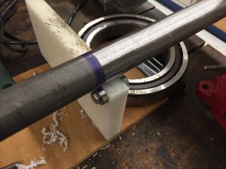
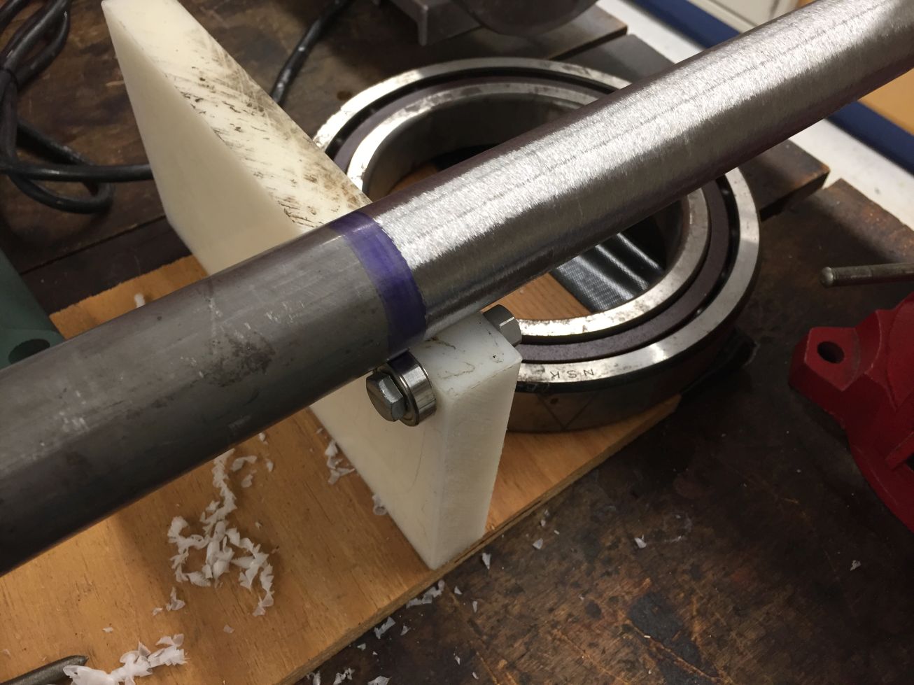
In the absence of a lathe, I had to come up with a more creative solution to decrease the diameter of the steel rod. I put together a jig with roller bearings and used an angle grinder, to create a sort of centerless grinding arrangement. It worked decently well, through the surface finish was rough.

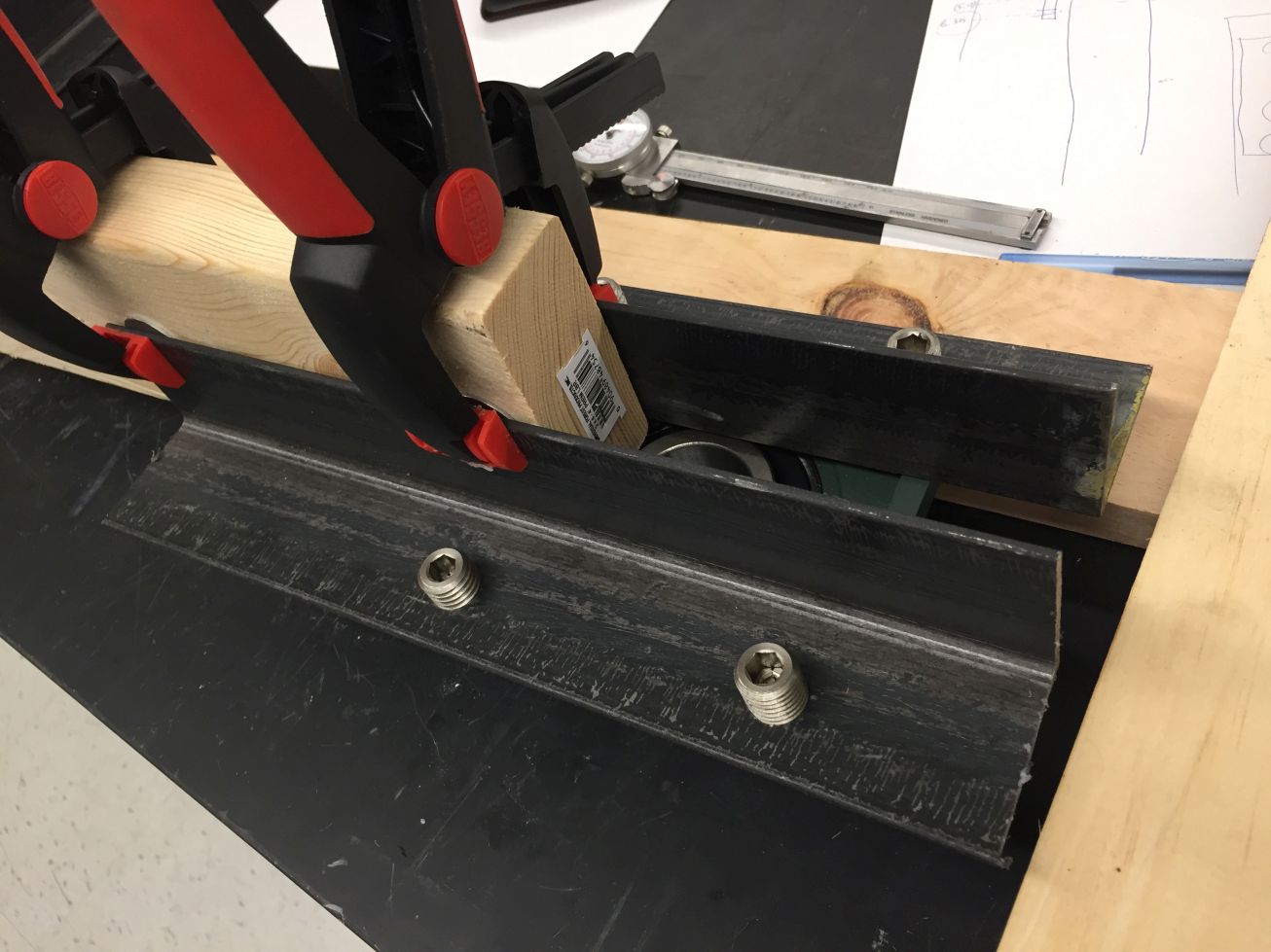
4 inch angle sections assembled to connect to wire ropes.
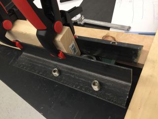
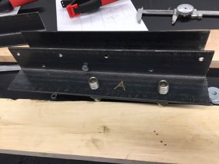
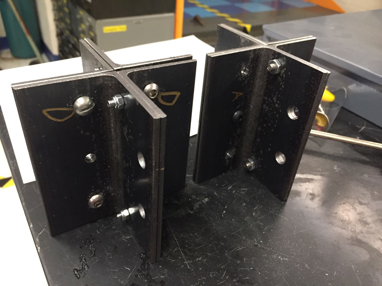
12 inch angle sections assembled to connect to bearings.

All the materials loaded into a car.
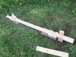
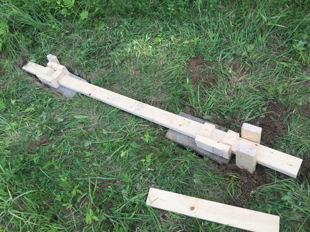
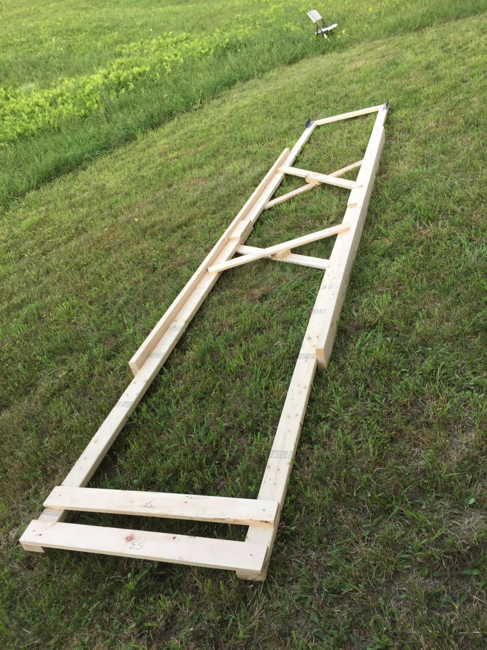
The main wood columns once assembled, and the ground foundation using leveled concrete blocks.
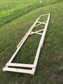

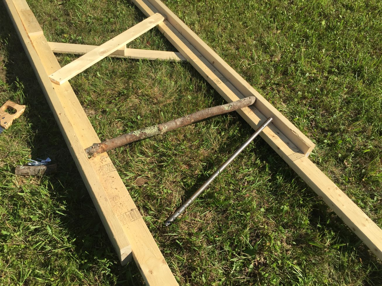
The rigid swing section with supporting cross-beams and a wooden handle.
Results
I was unable to test whether the wood structure supported by ground anchors would hold up to the expected swing loads, which was very unfortunate as that was the goal of this project. Still based on what it looked like from the ground, I believe the structure would have worked. Nonetheless I was able to draw a few conclusions from this experience:
- To achieve a true 360 swing I suspect it will be necessary to add a counterweight, and it is not just a matter of stabilizing lateral loads. Without a counterweight the swing does not store rotational energy as well, losing it due to air drag, and it will be difficult or impossible to complete a full revolution. Of course my goal was to test this directly, but I could not, so if you end up attempting a project like this, it would be interesting to see how necessary the counterweight really is. I would advise adding provisions in the design to have the counterweight present as it will likely become necessary.
- Strongly consider using natural structures - tall trees - as a way to support the swing. This vastly simplifies the construction process. On each end of the steel tube which is the swing axis, connect 3 wire ropes in 3-fold rotational symmetry with one going out and upward to a nearby tree, and two going out and downward to ground anchors. This provides 6 support points for a "floating tube" around which the swing can revolve. This will cut down the cost approximately 2-fold and materials and machining more than 2-fold, and will probably make the structure even more stable than what some solitary 4x4 beams could achieve.
- The connection of the swing to the ground needs to be part of the design, and existing practices such as gravel filling or concrete supports will be necessary. Flat ground is something we take for granted in modern society. There is the notion that ancient cultures had wheels but only used them for toys and trivial devices - the reason is because natural ground is not flat or level and wheels are useless then. The real success of the wheel comes from the existence of flat roads. Similarly, with existing buildings and houses and structures we expect that flat and level ground is just available. However natural ground is neither of these, and for a structure like this swing, where having a level and properly balanced assembly is necessary, this lack of flatness is a significant issue. Leveling the ground on the other hand requires heavy machinery and lots of effort. It would have been impossible to build this structure solely out of wood because of the bumpy ground, and I had to dig out holes for concrete blocks, which could be leveled and the swing structure built on top of the flat and level blocks. This is another reason why I recommend using the "floating tube" idea above and attaching the swing to existing trees, thus avoiding all the trouble of having to level the ground under the swing's columns and ensure the columns are both upright and at the same height.
- It takes a long time - on the order of a week - to construct and erect the structure, and this is after all the metal and wood parts have been machined already. To achieve a good return on investment, the structure should be installed permanently or at least for a long time.
- It is great to have large free-standing equipment to aid in the installation, such as a cherry-picker lift or a tall ladder. It also helps to have multiple people to move these large parts. Erecting a 20-ft column from ground level is possible but will require a secondary beam that is perhaps 8ft tall and is rigidly connected to the main column. The shorter beam is pulled to the ground, and the moment exerted on the main column aids in lifting it until direct tension to the ground anchors has enough of an impact to complete the lift. This is also how large cranes are erected, and I would recommend reviewing videos of processes like this (for instance this one) to get a better idea of what the design will require if it cannot be lifted with the aid of large machinery. Using large machinery, however, is the easiest approach both from an engineering and an effort viewpoint, so if machinery is available, it is a good idea to use it.
- Ground anchors and wire ropes are great. They were very easy to install, lightweight, and could support high loads. While their ability to last for long periods is questionable (permanent fixtures should use much deeper and probably concrete-set anchors), they were so convenient that I would recommend using them in similar projects.
- Individual wood boards can warp significantly - on the order of 0.5 inch even towards 1 inch from the ideal straight profile. There is thus a preference for using actual 4x4 beams instead of a pseudo-4x4 assembly made out of multiple 2x4 boards. This also greatly simplifies assembly. Using 4x4 beams was my original design, however they were not present in the store when I was purchasing supplies, and the limited time frame meant I had to proceed with what they had. It was not a good experience and I would recommend avoiding such an approach of assembling multiple 2x4s to make a bigger beam, at least for a project such as this. The warping of larger profiles will generally be lower, however it will still occur, and thus the design should include ample spacing between the columns and the moving parts so that no interference occurs (and yet another reason favoring attaching to trees instead of building columns).
- All steel parts should be painted to avoid corrosion. The corrosion is already visible following the first night spent outside with condensation and dew. I expected this from the beginning and the project wasn't meant to last long anyway so I did not paint it, but if you are looking to make a permanent structure, the paint should be included as part of the design, including provisions to paint the wood-facing metal surfaces prior to assembly.