Recently I have been interested in learning to identify constellations and use them for orientation and navigation, with initial work outlined in the article on rigorously scaled constellation maps. While I have learned the appearance of major constellations by practicing finding them in the sky, their changes over the course of a day or a year are still difficult for me to visualize. The motion of solar system objects in the sky (discussed more in this article), relative to my position on earth and to the time of day and year, is also a topic of interest which is not sufficiently conveyed by maps and static images. It would help my visual memory if I could project points (physically onto walls) in spherical coordinates, calculated based on known coordinates of celestial objects, and observe how the scene changes over time. For this, some way to generate large angular size projections is needed.
One possibility is the use of AR headgear. The main drawback is that it lacks the wide field of view which I would like to have in this project to recreate the visible angular size of the night sky, so that relative positions of constellations may be appreciated. However it should be noted that AR hardware has improved a lot since I used it a few years ago, so wide field of view AR displays may be more readily available. This sort of project would be much easier to implement in AR than in hardware projection as done here, and would likely offer improved functionality. Another possibility is the use of a fisheye lens to project points over a wide angular range. With recent developments in optics for "360 cameras", which use two wide-angle lenses to capture high-resolution images in any direction, taking the camera apart and inverting the optical path of one such lens would effectively project points anywhere on a hemisphere as desired. This would be straightforward in principle, but would require special optical components, so I did not proceed with this. For someone seeking to make a similar device I would recommend exploring this approach rather than using the tedious mechanism described below. As an example, this video shows the product "Global Imagination Magic Planet", which uses a regular video projector and a fisheye lens to project images inside a globe, covering most of the globe surface.
What I chose instead provided the least flexibility and display resolution, and was comparatively difficult to make, but it was a laser projector so would work without focusing in any setting and would cover a true (nearly) hemispherical angular range. The idea is to use a few hundred inexpensive red laser diodes arranged around a mirror which can reflect the laser beams in all outward directions over time, and then precisely (at the sub-microsecond level) time when individual lasers would turn on and off, so as to project an apparent point in some known 3D direction. There are some good matches between the application and the device here: plotting stars only requires a few points to be drawn (no high resolution text or graphics) which is easy by flashing a laser on and off at a specified point, and the device is to be used in the dark which means the laser does not need to be very bright (no need to search for expensive high-power laser diodes). So I thought that while an unconventional approach, this would be a quick project to demonstrate the proof of concept. In reality this project turned out to be quite challenging to design, with the constant frustration of knowing that it could be possible in principle but is not readily achieved in practice. Numerous initial unsuccessful designs are described here.
In the initial design of a doubly-rotating mirror, the properly calculated reflection of the laser beam deflected along two axes instead of one, resulting in messy disjoint spiral patterns rather than nice circles as hoped from an incorrect intuition. However this presents an opportunity - since a mirror can reflect a beam along two axes, there is no need to have a second spin axis. Rather, a properly angled mirror spinning along one axis will generate the desired projection pattern. Compared to the doubly-spinning mirror, there is a lack of laser multiplication, which means the number of lasers will need to be physically increased. This is not wholly negative, since the effective laser spot velocity is lower, the timing accuracy requirements are reduced and the projected pixel is brighter (the laser is on for a longer period of time). As we already anticipate being limited by laser brightness, reducing the multiplication factor presents an advantage. Although aligning 256 lasers instead of 128 doubles the required effort, the laser alignment mechanisms already need to be designed and are readily accessible, so mechanically this is not a challenge. The more pertinent limit ends up being the overall size of the projector, where we must squeeze the laser diodes tightly together in a two-circle arrangement to remain within a 40 cm bounding box (for the sake of mechanical rigidity of the optical path and ability to carry the projector).

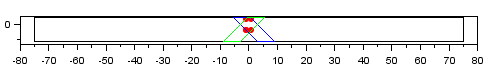
A 3D plot of the reflected laser path for four laser diodes (four different color curves) in the XY plane (LD locations marked with dots). Adding more lasers increases the density of these curves for higher pixel resolution. The laser path from the LD at (0,-1,0) to the mirror reflection at (0,0,0) and to the red projected curve is illustrated with a red dashed line. The other curves are generated when the mirror rotates to face other LDs.
A script was written to calculate the reflection of a laser beam from an angled spinning mirror. The spin axis is defined to be the vertical +Z, so the spin plane is XY. The mirror may be angled relative to an axis perpendicular to the spin axis and mirror normal. The laser in turn may be placed at some angle along a unit circle in the XZ plane. Each of these conditions results in different projected beam patterns. After considering different laser diode and mirror angles, I chose the configuration of laser diodes emitting towards the origin in the XY plane, and a mirror oriented at a 45 degree angle to reflect a laser towards the top of the sphere (+Z) when the mirror normal is rotated in line with the corresponding laser diode. This is easy to fabricate since all lasers are in one plane, straightforward to align since all laser curves intersect at the +Z point, and easy to split into pixels since all laser curves are similar (differing only in angular shift along the spin axis). Furthermore, by aligning all the lasers onto one point and moving the mirror so this point is centered on the spin axis, the reflections are an effective simulation of a point source.
It turns out there is a further mathematical advantage of the above choice of angles. I have tried to derive an expression for reflected laser beam angle from an angled spinning mirror in terms of spherical angle (rather than rectangular) coordinates, however there are so many terms in the resulting expression that it is possible an error has snuck in. For the moment, I place more trust in the "brute force" rectangular coordinate results from the simulation script. There is an intuitive way to understand this geometry: if we consider a stationary angled mirror centered on the Z axis and a laser diode moving around the mirror in a circle in the XY plane, always pointed at the mirror center, then we can imagine a virtual laser diode in the "mirror world" whose position is reflected about the mirror plane, and the reflected laser beam will be in the same direction as the beam emitted by the virtual laser diode. At a 45 degree angle, a circle in the XY plane centered on the Z axis gets reflected into a circle perpendicular to the XY plane and passing through the Z axis. Therefore, the spinning 45 degree angled mirror is similar to spinning a semi-circular array of laser diodes in a plane perpendicular to the XY plane. With uniform timing of flashes as the mirror rotates, the projection looks like the arcs of longitude on a globe. The results from these considerations are the same, and somewhat surprising. With a 45 degree mirror and a laser aimed at the mirror center along a horizontal line, the angular position of the reflected beam is
projected_theta = sign(mirror_theta-laser_theta) * (%pi/2) + mirror_theta
projected_phi = (%pi/2) - abs(mirror_theta-laser_theta)
Note that both angular terms have a linear dependence on mirror_theta, which is in turn linear in time for a fixed speed motor. This means that a pixel basis linear in (theta,phi) may be converted directly (algebraically) into laser timing patterns. Each laser diode is offset by an integer multiple of dl_theta from its neighbors, which corresponds to an integer multiple of dt, the time required for the spinning mirror to turn from facing one diode to facing the next. Therefore the same time basis of discretization to generate pixel points may be applied to all lasers in the projector, which greatly simplifies the laser pulse timing. With a constant mirror speed, we need to output pixel info and a fixed-duration pulse every dt, and the pulse may be globally applied.
There are many promising aspects about this approach, however with the 5 mm or even 25 mm square mirrors considered previously, it is not possible to reliably reach low angles, so only the upper portion of the hemisphere may be projected (limited mirror acceptance angle). There is no pressing technical reason for why this could not be extended, as the mirror is capable of reflecting at very low incidence angles (less than 1 degree). The mirror then should not be square but rectangular, much wider so that its acceptance angle within the XY plane is close to 180 degrees. This will return much of the acceptance coverage of the doubly-spinning mirror design, with minimal added difficulties. The challenge then is finding an appropriate aspect ratio mirror.
A projected view of the mirror size as seen by the laser diode as the mirror spins. As reflection angles near the horizon are reached, the required mirror size quickly balloons towards infinity due to the tangent relation. A 150 mm wide mirror tilted at 45 degrees, simulated in this plot (black rectangle as seen at 0 degrees incidence angle), is just adequate to fit a 2 mm wide and 4 mm tall laser beam (the corners of which are marked by the red points in the plot) at 87.7 degrees incidence angle (blue and green polygons).
Such a mirror is actually difficult to purchase new - even optical suppliers like thorlabs do not carry it, and I could not find a supplier online selling mirrors of this shape. One could cut a thin strip from a large sheet mirror, however then the mirror would be back-surface (carrying more of a negative impact at the intended shallow incidence angles) and probably with non-ideal edges or curvature. Luckily there is a way to obtain a long rectangular front-surface mirror for very cheap, by taking apart an old laser printer from the trash (or in my case, by purchasing two old laser scanner modules from ebay, with the anticipation that at least one would not be mechanically damaged on arrival). The laser scanner module contains the optics to scan a laser beam in a high resolution line to generate patterns that transfer ink to the paper in a laser printer. Typically this consists of a laser diode, collimating lens, cylindrical lens to generate a round dot from the elliptical dot of the diode, a metal aperture to clean up the beam shape, a multi-sided spinning mirror on a fancy ceramic air bearing with integrated motor and phase-locked loop speed controller, two extended lenses that linearize the travel of the laser beam along the roller and focus it at the proper distance, and a long mirror that reflects the laser beam down onto the roller (as well as a photodiode used to synchronize the laser data output to the actual laser position). It is the final long mirror that is a perfect shape for the proposed projector (it is also likely coated for IR wavelengths, which is close enough to the 650 nm red diodes used here). The fancy bearing and motor controller are tempting to use to spin the mirror, however they are designed for speeds such as 30000 rpm, and would not be appropriate for the 1800 rpm target for this projector. Overall, it is interesting to take apart such a module and try to understand the logic behind the engineering decisions made, to learn about precision optical design applied on a mass scale.
The appearance of a wide spinning mirror brings to mind the shape of a spinning radar bar such as used on boats and at airports, however the method of operation does not really have similarities. The radar bar is wide to generate a phase shift along the internal antennas to focus the beam along a well-defined bearing outwards from the spin axis and perpendicular to the long side of the radar, with less importance of the vertical beam pattern (which spreads out by diffraction) so that objects at different heights are detected. The mirror in this projector is wide to allow for grazing-angle reflections of the incident laser beam to expand the laser beam coverage of the hemisphere; at optical wavelengths the relatively short vertical height of the mirror does not worsen the diffraction spreading of the beam.
It is necessary to provide a means to synchronize the timing of the mirror motor to the timing of the laser pulse signal. In the laser printer scanner module, this is done by a photodiode that detects the laser after every mirror pass, anticipating that in between the mirror speed remains constant. Since the rotor speed in the projector is over 10 times slower (and there is only one mirror rather than multiple in the laser printer), and the drive mechanism is not as intricate (brushless motor with ball bearings and a hobby grade speed controller, rather than an air bearing motor with phase-locked loop), I anticipate needing timing signals more than once per motor revolution. For this a disc with 128 rectangular cutouts (256 transition edges dark-light or light-dark) is used along with a fast photo-interrupter. Further anticipating timing jitter due to the photo-interrupter itself, the signal from the interrupter is used to latch a timer value, which is then filtered in software, setting another timer which controls the laser data output. This scheme requires that the jitter is less than 50 % of the duty cycle, which appears feasible. One of the cutouts in the encoder disc has a slightly longer transition period, which is used to identify an index position for the mirror. This is important since the lasers must be synchronized to the absolute theta angle of the mirror.
The timing of the laser pulse, while not particularly stringent at approximately 1 microsecond, must nonetheless be hardware-controlled, because it will be unpleasant to watch projected dots wander around due to poor timing such as interrupts and delays in the software (which also has to process communications with the controller interface). The laser pulse start and end should be defined to within 100 nanoseconds from a corresponding edge transition of the photo-interrupter, which may be low-pass filtered in software to itself be stable to within 100 nanoseconds. Any data transfers along with their set-up times must complete before the laser pulse rising edge. This is all handled by the FlexIO module of the Teensy 4.1, building on the experience gained with the acoustic field camera project. In the AFC, 256 bits of data was shifted in to the FlexIO module on 8 parallel lines over 32 cycles, and here 256 bits of data are shifted out of the FlexIO module on 8 parallel lines over 32 cycles.
The most flexibility in terms of laser diode control is achieved by shifting out 256 bits in each cycle, however if we need 100 nanosecond timing resolution, the data transfer rates are very high, which has negative impacts for both PCB design and CPU load. Since we are displaying star positions and not very dense images, it is conceivable that a scheme which uses 8 bits to specify a laser number would be more efficient, so at each cycle only 1 laser is powered on, and which laser that is, is specified by the bit code. Then we only need to shift out 8 bits in each cycle, but only 1 laser may be powered on. Alternatively, we may have special codes for on and off (which would set or reset a flip-flop, for example) and then a different laser may be powered on or off at each cycle without disturbing previous ones. These possibilities were simulated using randomly-placed star points to determine when they would not be capable of rendering the scene correctly. The results were discouraging since with as few as 10 stars, the chance of improperly drawing the star (error exceeding the pixel pitch) was approximately 0.5. Thus I was led back to the 256 bit shift, and here the linear nature of the reflected spot position over time really helps the design. Namely, while the pulse timing resolution must be within 100 ns, the data only needs to be shifted out once per mirror position or within 65 us. This means we can use low speed (approx. 1 MHz) data output clock, and a fast hardware timer for the laser output pulse, which is distributed globally only once per cycle (pixel calculation). The data buffer requirements are also reduced, which keeps the CPU load manageable.
Note that while the reflected spot (theta,phi) are a linear function of time, the spot velocity on the surface of a unit sphere is not constant (calculation). The spot appears to speed up near the horizon, and to slow down at the top of its travel. However this variation is small relative to its average speed, so is not considered in the pixel calculation. This causes projected pixels near zenith to be slightly narrower and brighter.
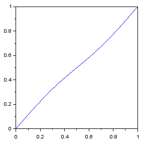
Plot (in path length units) of spot distance along its path (vertical) vs mirror angle (horizontal) along one laser's reflected path (upper half of "8" shape), with the reflection falling on a spherical surface. For the case of a 2 m sphere radius and 30 frames per second, the laser path length is 7.6 m and average speed is 458 m/s.
Like the acoustic camera, the projector uses Power over Ethernet (PoE) with a AG9205S module that outputs up to 3 A at 5 V. This powers the Teensy and (up to) two boost converters. The first boost converter generates a 12 V output for the mirror motor. It is possible to install a second boost converter to generate a variable voltage for the laser diodes. The diodes are nominally rated for 5 V and contain an integrated resistor to limit the current to 20 mA. It is likely that at low duty cycles (below 0.01) the diodes can handle higher currents and result in a brighter spot. Testing showed that the diodes cannot tolerate 12 V for any period of time (immediately burning out), but can tolerate 10 V for long periods (even up to 0.5 seconds) without any apparent decrease in brightness when operated at 5 V afterwards (note, however, that at short pulse durations the circuit inductance may be a limiting factor, the measurements I carried out were only a rough indication). Since I was not sure how bright the laser spots would appear in the final projector, I added the capability to raise the laser diode voltage to increase the brightness if necessary. Hopefully this will not be necessary, in which case a bypass wire delivers the input 5 V directly to the laser voltage plane (after filtering to avoid interference from the rapidly switching LDs), since this improves diode longevity and eye safety. As an alternative, I found manufacturers that could supply higher power laser diodes in the same package, but I would like to avoid this option due to eye safety considerations (this projector can direct a laser beam anywhere in a hemisphere, after all, so there is not really any safe way to approach it; occasional viewings of the laser beam are to be expected and should not be dangerous to ocular health).
This was supposed to be a simple component, something to hold each laser diode (LD) so it could be attached to the projector base, however this proved to be so tricky that it almost wiped out my motivation to complete the project. The laser diodes, bought in bulk, come as a small (about 6 mm by 6 mm square) circuit board (with laser diode wire-bonded to one edge of the board) pressed into a cutout in a 6 mm diameter cylinder, onto which is threaded another 6 mm diameter cylinder which houses the collimating lens with a preload spring. This cylindrical package does not present any nice attachment points. The requirements of the LD holder are:
The optical interference requirement was particularly severe. It is not too difficult to make a 3D-printed kinematic mount, but the size of the mount would be much larger than the 6 mm LD cylinder. Here the entire holder must be narrower than 6 mm, because to keep the projector size from getting out of hand, the LDs are packed very tightly so that all available space within the LD plane is taken up by either the copper cylinder sides or the 2 mm wide laser beams, which leaves no space for holders. Also I have to be very minimalistic with the adjustment axes and mechanisms for each holder, because any extra hardware incorporated in the holder will be multiplied by a factor of 256, increasing cost and complexity. The tolerances are also very tight - the angular resolution requirements mentioned above mean that a shift of 0.1 mm between the LD back and LD front level (relative to the ideal LD plane) would lead to a visible shift in LD beam projected spot. Thus UV-cured resin 3D printing was chosen as it offered the necessary sub-mm resolution, which proved to be absolutely necessary in developing this part. I bought an LCD-based printer a few years back that had been sitting in a garage with no climate control (at my grandparents' house, there is no garage in my small rental studio apartment) for that time so I was hesitant to use it as I feared this mode of storage destroyed the printer or the included resin. To my surprise, both printer and resin worked well on the first try, and the parts were much higher resolution than anything I've done with FDM extruder printers. Moreover, I was not particularly careful with the resin that was left in the printer, other than consistently working in a dark room with red lights to avoid premature UV curing of the resin. I left resin in the tray on the printer for many weeks (with the tray covered by a plastic sheet to prevent evaporation of the volatile fraction of the resin), and the resin still performed reasonably well after some mixing (it was slightly more viscous, as some volatiles had evaporated and some partially cured microscopic pieces from the previous print remained floating in the mix, which caused small holes in the print to be filled with semi-cured resin to a greater extent than if using fresh resin).
The general concept was that each holder would have 2 bolts - one would attach the holder to an underlying board with alignment holes and provide fine adjustments in theta, while the other would provide fine adjustment in phi. A tiny 4 mm diameter o-ring would act as a spring providing preload against the second bolt for the fine phi adjustment. Coarse adjustments of theta and phi would be done by using a blob of hot glue when attaching the diode to the holder, and manually holding the diode in the correct orientation as the glue hardened. Tight packing of the LDs was achieved by making the holder operable in both forward and reverse orientations, so that the adjustment bolts would be out of the way of the LDs. Design of the part was completed using OpenSCAD.
In the first prototype, the phi adjustment bolt would thread into the 3D print resin, which I thought would be cheaper than requiring a nut for this purpose. Due to the fine pitch of the M2 bolts, the resin could not hold a thread very well, and the bolt would form the threads but then tear them out and provide no adjustment. Also I printed this design from the side, which meant the first resin layer (which tends to solidify in a wider region than the design shape) bridged the gap between the adjustable section and base section, so there was effectively no phi adjustment. In the second prototype, a section to insert a nut was included, so both bolts would be threaded into metal nuts, which was a good choice for better usability of the mechanism. I printed the part from the back, so the adjustment mechanism worked as designed. I thought this might be good enough to test out alignment of multiple LDs, for which I used a small CNC mill (that I bought back in 2020). I drew up the hole locations in DipTrace using the "radial placement" feature, then exported the N/C drill file, opened that file in FlatCAM, generated a g-code output there to drill 1 mm and 2 mm holes, then loaded that file into Candle which sent the commands to the CNC mill. Then I attempted to mount 3 LDs in the holders (SLA 3D printed) and align them to point at the same spot within the design alignment accuracy. This process mostly worked but the hot glue attachment proved to not be sufficiently secure - it was possible to shift the LDs out of alignment by applying some loads to the electric wires of the LDs, and sometimes the LDs would simply come unglued from the holders altogether, which would be disastrous if it started happening with 256 tightly packed LDs to keep track of. (Copper is not a good material for hot gluing, as due to its high thermal conductivity the glue solidifies without sufficient time to deform and make a good bond.) Also the reversible orientation of the holder made assembly more confusing and did not help alignment, since with the reverse orientation both adjustment bolts would be directly under the LD wires, so to fit a hex key into one of the bolt heads would require pushing the wires out of the way, which in turn would deflect the LD pointing position.
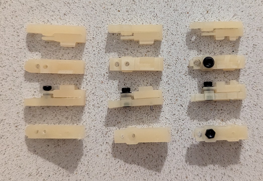
Left to right, 3 iterations of holder design for glued LDs.
For the next prototype, I made it non-reversible, so all LDs are attached identically, and the adjustment bolts are all under the laser beam path where they can be easily accessed from the top. This required giving up some of the compactness (and not for the last time) by slightly increasing the outer diameter of the projector base from 400 mm to 408 mm. The glue problem, however, felt like a real show-stopper. For a few weeks I was in a bad mood because I could not think of a better solution. Using the hot glue for coarse positioning is really a great approach, because it is easy to align the diode by simply holding it while powered on and putting the beam on a pre-drawn alignment dot. Doing this by other mechanical means would be relatively bulky, expensive, and more complicated to design. However it would be unacceptable to risk LDs coming loose after alignment and ruining the device.
The first design for the LD holders was based on gluing the LDs into place. Here the holders are bolted to an unmilled circuit board, and LDs are glued in place for testing alignment accuracy and stability.
Since it would not be possible to grab the LD cylinder by the sides (as that would interfere with the optical pathway of neighboring LDs), and glue was insufficient, the holder was redesigned to grab the LD cylinder from top and bottom. I thought that one bolt could be used for both phi adjustment and preload by having the bolt push down on the LD, and the LD in turn compressing the o-ring underneath. The o-ring would serve a dual purpose of fine adjustment and constant force for holding the LD. However this design requires closing the force loop through the resin of the holder, which can be expected to plastically deform (creep) over time and remove the preload force and all associated advantages. Another few frustrating weeks followed as I kept trying to find a way to apply a constant force to the LD without relying on the plastic of the holder. Whatever the solution, it would have to be cheap, scalable, and reliable to consistently function in 256 holders. A metal component is the logical choice for applying a preload with a spring, but how can this be incorporated into a space-constrained 3D printed design, and without causing deformation of the plastic or movement of the LD? Eventually I determined that staples would be a good fit for the application: thousands of staples can be easily purchased, they are adequately small, and they are made from steel which allows them to act as springs. In the next iteration, the force loop was made shorter, with the functions of preload and phi adjustment separated, so that the bolt and o-ring were used for phi adjustment, and the staple was used for LD hold-down preload. Again a slight over-solidification of resin caught me off guard, now due to the small cutouts designed to fit the staple thickness, which made it impossible to actually insert staples into the part. The plastic columns holding the LD in place were also too thin to effectively counter the preload force.
Improving the part and printing process to simplify the use of staples as spring preload, I reached something that felt close to a working design. The prospects for finishing the project didn't seem quite as grim. I printed 8 holders of this design, and was able to align 7 LDs to converge at a point. The LDs would drift over time, but the magnitude of this drift was within the design pixel pitch so was not a major concern. A bigger concern was inconsistency in the LDs causing difficulty in coarse phi adjustment. With the original glue based approach, a large error in phi could be easily handled by manually angling the LD as the glue solidified. With the clamp design, the angle at which the LD could be held was effectively set to one value, except for the fine phi adjustment by the adjustment bolt. The fine adjustment of about 0.1 mm range was insufficient to handle the observed variability in LD manufacture, which caused some laser beams to be emitted at angles above and below the LD cylinder center axis, requiring a total adjustment range of about 0.5 mm. This could be achieved with tricks such as putting a washer under the o-ring to increase phi or removing a washer from under the o-ring to decrease phi, but this also requires similar gradations in the length of the adjustment bolt and thin washers which are not readily purchased. It can also put excessive strain on the plastic hinge for the phi adjustment mechanism. Again I was left without much certainty as to how this project will advance.
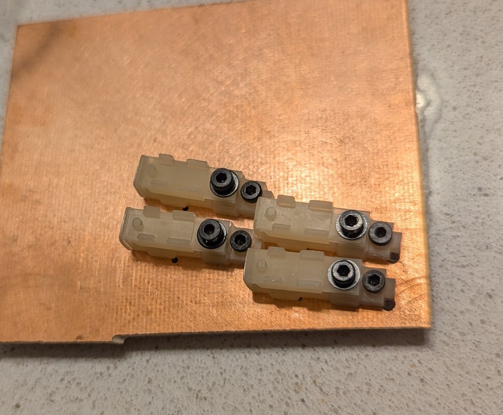
Aligning 4 LDs in holders so they all point to the same spot on a card, and the resulting projected dots on a wall if the card is removed.
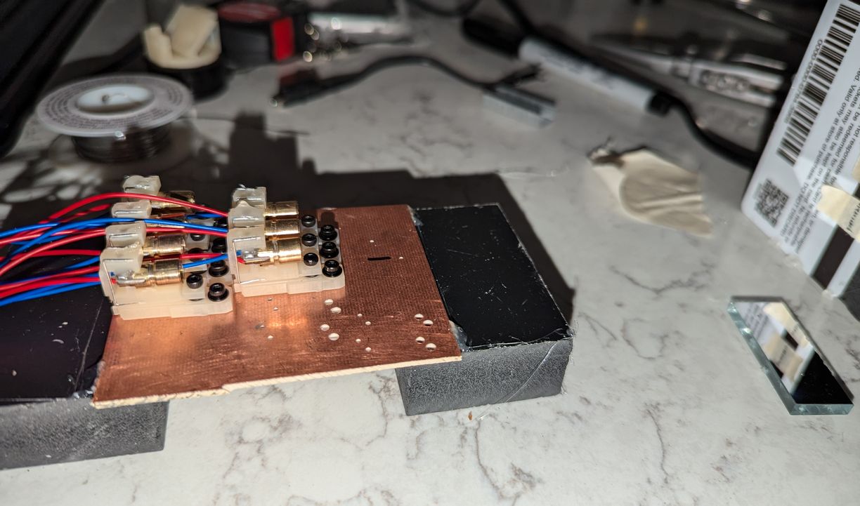
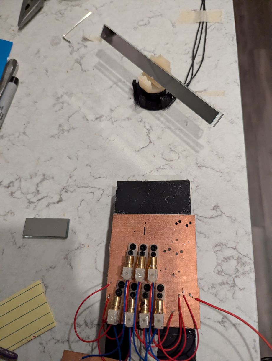
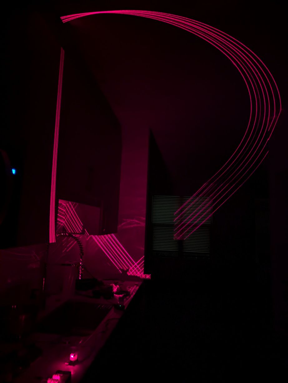
Increasing from 4 to 7 LDs in holders on the test PCB, again aligning to the same spot on a card, and then installing a spinning mirror to validate the reflection calculations and general functionality of this approach. This assembly was glued to various surfaces in the kitchen area of my apartment for many days, to provide a long projection distance to the next wall so the holders could be tested for stability over time, although this made cooking more difficult. The traced out curves looked like the expected "upper half of figure 8" shape (from simulation) for each laser, overlapping in a point at zenith. The curves do not look too clean in the photo because some parts of them are caused by stray reflections from the back angled surface of the mirror; the lasers are on continuously and not synchronized to the motor rotation.
In the previous version, the LD was held in the clamp section by a length of approximately 4 mm at the back of the LD package (which is all solidly connected), with two columns and a line-cylinder contact providing a strong fix of LD rotation (which is important as the emitted beam is rectangular in profile and should be oriented with the short side horizontal, to increase acceptance angle for the mirror), and two planes forming a V-shape groove providing a weak fix of theta angle (which allows for coarse adjustments to account for LD manufacturing tolerances before the LDs are glued and fine adjustment is undertaken). This was changed to use more of the LD package length, which meant that the preload was applied to the back section and the V-shape was contacting the front threaded-mount lens holder section, however the spring preload inside the LD package and fine tolerance of the threads between the two sections meant that this choice did not degrade pointing stability. Further, the perpendicular-plane V structure was changed to a perpendicular-line V structure, which when contacting the LD cylinder would allow for coarse adjustments in both theta and phi. Instead of a single column height at the back of the LD, there was a stepped section, such that by moving the LD back one step, its back end would also move up one step, thereby angling the LD down in phi as the contact line of the cylinder with the V shape could be assumed to remain at constant height. This design requires that the LD wires are centered with regard to the LD package (so as to not hit the stepped section), which was also not the case for all purchased LDs, however this could be fixed fairly easily by touching with a soldering iron and relocating the wires into the center.
Having made this design change, I thought I could use a thicker resin section for the clamp and avoid the staples, however predictably the resin deformed over time under load and did not make an effective spring. In the next iteration I added the staple section back in, but the cutout for the staple insertion caused the stepped structure to be printed warped. Over a few days, I also noticed creep in the structures directly in the path of the preload force from the staples. Now on the 10th iteration and 6th month of trying to improve the design, I was ready to be finished with this part. I thickened sections that handle the preload force, connected the stepped structure to the hinge for better printing, and adjusted the heights of the LD contact points by +-0.1 mm to account for resin under- and over-curing on different angled slopes of the part. Finally the LD holder seemed to be in a good enough state to justify advancing with the rest of the project. It provided 5 coarse steps of 1 degree in phi and fine adjustment to about 0.1 degree, with slightly larger amounts in theta. The hold-down force was consistent and plastic deformation due to creep was acceptable (deformations as small as 20 micrometers, or about the thickness of a piece of paper, cause an observable displacement of the laser beam spot). The pointing stability was within the design goals for the project (half-pixel pitch of approximately 0.35 degrees). There were also a number of small improvements along the way, such as designing a taper section that would make it easier to detach the LD holder from the print bed, including an alignment hole for a 1 mm diameter dowel pin (and ensuring this hole didn't get filled with half-cured resin), fine-tuning the opening for the o-ring compression (with 0.05 mm making a difference in performance), and constraining the outer edges of the holder to not interfere with neighboring holders upon installation in close proximity in the final assembly (including extents of movement of the neighboring holders due to the adjustment mechanism).
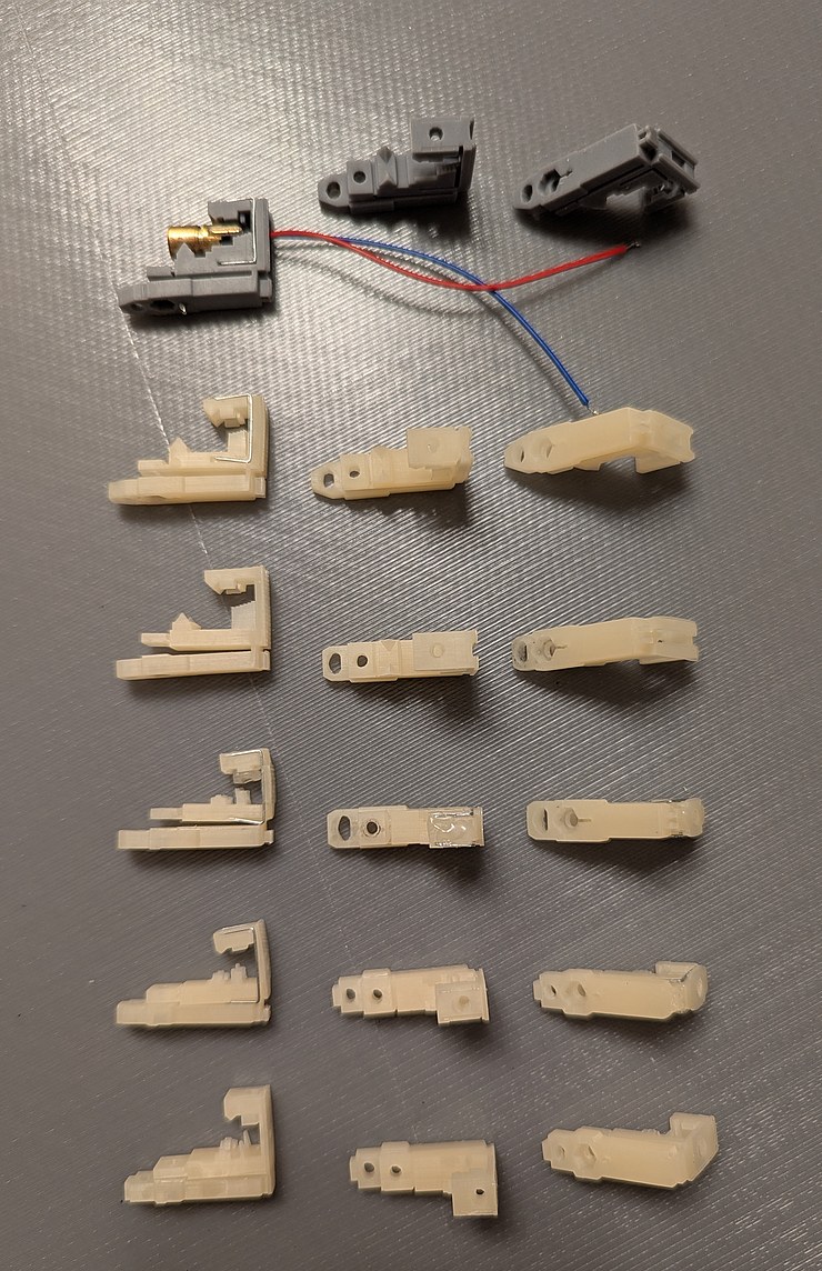
Bottom to top, 6 iterations of holder design for clamped LDs.
But the trials were not over yet. As I assembled the circuit boards and tested the motor, the printed LD holder prototypes were on a table out in the room, exposed to ambient light. Despite lengthy curing in a UV enclosure, apparently some of the resin had not fully cured, so over weeks the LD holders became warped. I guess sometimes it is better to take things slow - this delay allowed to me notice the warping problem before going to full scale production of the LD holders. With some thicknesses of the holder exceeding 3 mm, this warping was not too surprising, although I think it is resin-dependent. In earlier prototypes I used beige resin which seemed to have less warping than the grey resin of the last prototype. Perhaps this is because the grey resin blocks UV light more effectively so the resin inside the thick wall takes longer to cure. The warping of the part was away from the space that is surrounded by two resin pieces (thereby receiving less light), which is consistent with ambient UV light causing shrinkage of materials that are outside this surrounded space. Luckily the direction of the warp was such that it would not have worsened the performance of the installed LD holder. However, if this holder were installed before fully curing, the bottom surface would be blocked by the PCB, in which case warping might take place away from the PCB, which would not meet design goals. Therefore the walls were made thinner and with extra openings to allow UV light more direct access to more of the resin volume, for better curing prior to installation. Clear resin could also be used, as UV light could better penetrate through thick walls to the interior of the solid for uniform curing (although after attempting printing with clear resin, this problem was also observed; maybe in addition to the light curing mechanism there is also the need for diffusion of volatile components out of the solidified resin, which would also favor warping towards the outer surfaces).
OpenSCAD rendering of the final LD holder design.
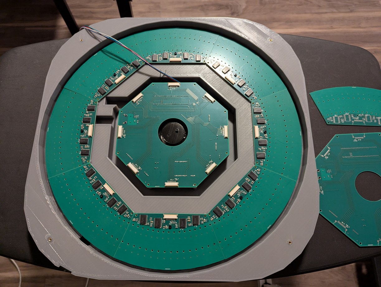
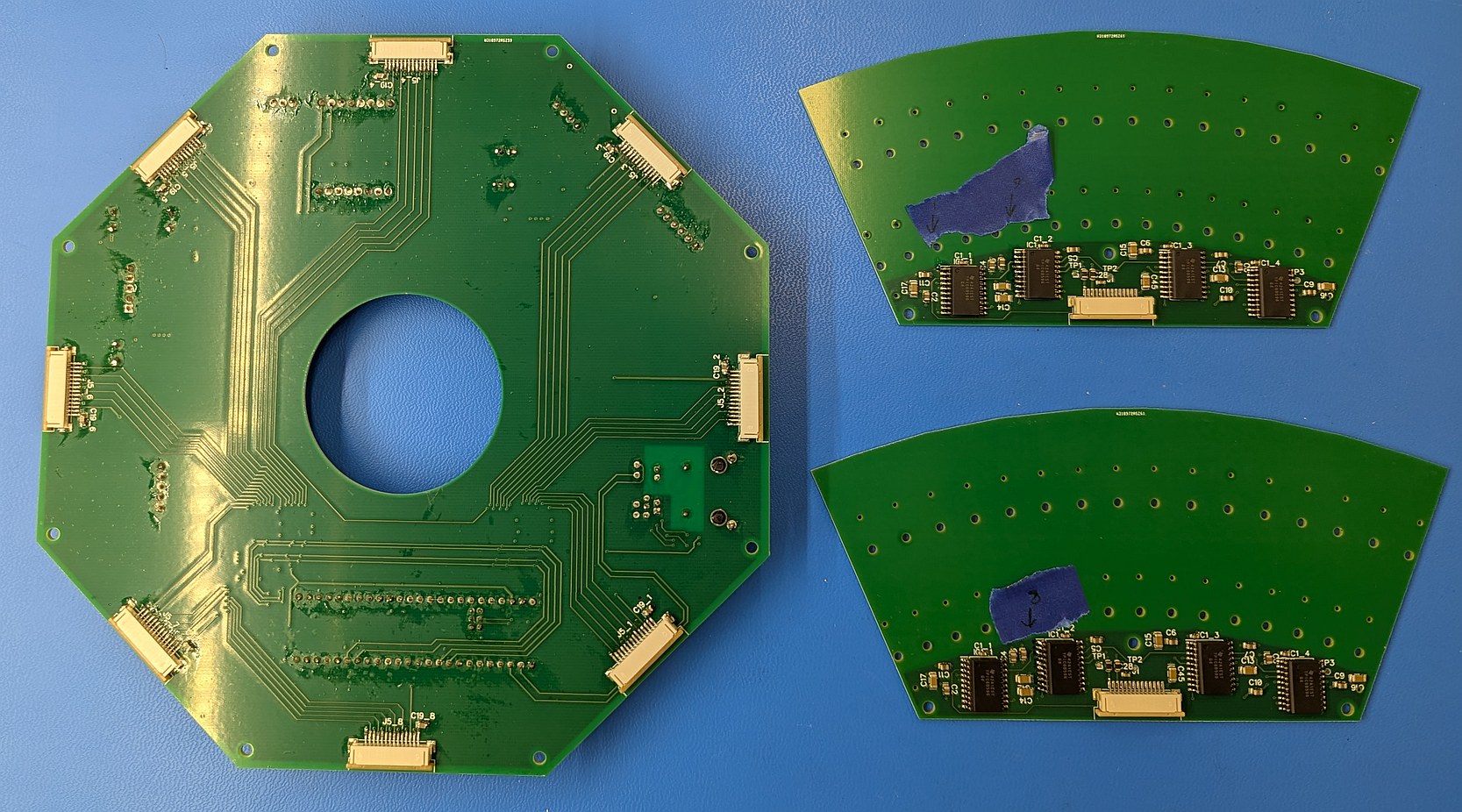
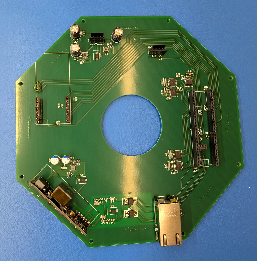
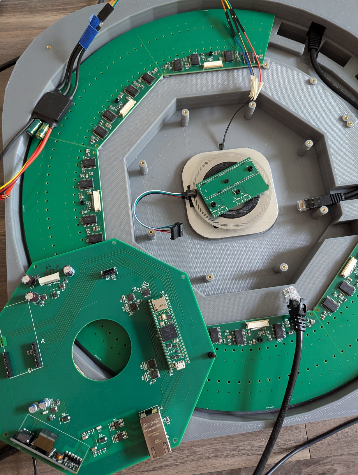
I designed the main circuit board with PoE power supply and Teensy 4.1 with ethernet connection, and 8 outputs to LD boards. Each LD board houses 32 LDs in a 1/8 circle pattern, with 4 8-channel TPIC6B596 power shift registers which are connected directly to the LDs (this was a great choice as it decreases the number of components on the boards, and with the looming task of aligning the LDs, I was happy to make the PCB assembly as simple as possible). Having freshly read through Johnsons and Graham's "High Speed Digital Design" book, I tried to apply their best-practices advice when designing the boards. However I found that replicating their nice diagrams of clock distribution trace layout would leave no room for any other traces, and conversely adding other traces would make the layout no longer match the nice diagrams. I would feel like I perfectly understood the problem after reading a few paragraphs in the book, and then the elation would be crushed by all the other stuff that needed to be routed in the same layer and across the path of the signal, causing possible interference and cross-talk. I used a 4 layer stack on all the PCBs, hoping that a large continuous ground plane would cover up any suboptimal choices in the routing. The biggest exception is on the LD boards, the ground plane does not extend into the section of the board under the LD holders, to ensure a flat surface for the LD holders to sit on. When signals switched between top and bottom layers, I placed capacitors that would help couple the return current between the two inner layers (ground and 5V) near the signal vias. I also tried controlling the trace impedance for the signals to LD boards, at least roughly. At first I was so enthused with having the cleanest signals that I had a voltage translator (from Teensy 3.3V to 5V for the TPIC6B596), a buffer to parallel 1 signal to 8 boards, then another buffer on the LD boards to receive the signals, all with terminating resistors to avoid reflections. In principle this is a decent approach for large distances (if this is done, the buffers should be inverting to better maintain duty cycle), but as the entire system fits within 50 cm, this many buffer ICs would be excessive. In the final version this was reduced to a single buffer (SN74ACT8541PWR) with source termination resistors, and a trace layout that places the 4 receiving TPICs (on each LD board) in a chain rather than star pattern, so the impedance of the trace to the ground plane was mostly constant. The buffer is capable of accepting 3.3V input for 5V outputs, and of driving lines as low as 50 ohm impedance. I use a flat ribbon cable to connect the LD boards to the main board which has neighboring line impedance of about 80 ohm, so I chose the minimum trace width of 0.15 mm for the clock and signal lines which I expected to give about 71 ohm, and a 63 ohm resistor on the buffer output (which I estimate ranges from about 6 ohm to 12 ohm). This is far from perfect matching, but is also better than no matching, so I would expect performance adequate for the task. Really since the clock here is barely above 1 MHz this effort was more of an exercise than a necessity, however it would be a great frustration if I go through all the trouble of building the device only to end up with randomly flickering and jittery outputs, so it seemed prudent to design for maintaining signal integrity and minimizing interferences.
A predictable source of interference would be the current spikes when turning the LDs on and off on microsecond time scales. To reach full brightness during that short pulse, there should be a low impedance path to the LDs that are powered on, and to maintain voltage stability elsewhere in the system, this current spike should be attenuated by the time it reaches the main board. In the worst case, half of LDs would need to turn on simultaneously (as the other half would be facing away from the central mirror), which would correspond to 2.56 A with a desired rise time below 1 us. To allow this, I placed numerous capacitors on the LD and main boards, with the logic that multiple spread-out low value capacitors are better than a single high value capacitor for equal total capacitance (because the multiple spread-out ones have less parasitic inductance). I placed the capacitors at strategic points by the ICs where they could serve a double function of helping return currents cross between the top and bottom layers. I used 1206 package 22 uF, 0805 package 1 uF, 0603 package 0.1 uF, and 0402 package 0.004 uF ceramic capacitors. The different size packages are great when placing the components by hand, but the primary advantage is the lower inductance (including closer proximity placement to ICs) of the smaller packages which becomes increasingly important at lower capacitance values. The capacitors specifically for ICs had their own traces to the IC power pins, while others for general voltage stabilization were connected by vias to the power planes. Also the LD board had ferrites (approx "2200 ohm" for the logic 5V and "1000 ohm" for the LD 5V, the latter being rated for higher current) immediately after the flat cable connector, to prevent local voltage oscillations from being radiated by the ribbon cable. On the main board side of the connector, the LD power pin had a 1 uF capacitor to further smooth out changes in voltage from the LD switching, before connecting to the large (low impedance) LD power plane. This power plane was connected to the logic 5V power plane through a 1.5 mH inductor and two 100 uF electrolytic capacitors (and two 22 uF ceramic capacitors) with a 15V reverse voltage rating protection diode. The hope was that by the time the current spike passed through all these elements, it would result in a slow change in voltage that would be within the control bandwidth of the PoE 5V supply which powers the whole system. Similar electrolytic filtering was used to send 5V to the boost module for the brushless motor speed controller, which further had its own onboard electrolytic capacitors.
While I had the electrical side of the circuit boards fairly well defined, the mechanical side was still in development. In particular, I needed to know what size the boards should be and where the mounting screws and cable connectors should be located. For the LDs, this meant I needed to know the shape of the LD holders and their mounting hole patterns. For the main board, this meant I needed to know the shape of the motor, mirror, and encoder assembly. For both, I needed to know the relative sizes to pick the right flexible cable to connect the boards. The relative vertical levels of the boards also need to match the motor, mirror, and encoder, for proper optical alignment of the laser beam plane with the mirror center, and for adequate clearance of components under the main board and any associated wires from the spinning encoder ring underneath the board. All of this in turn informed the design of the case for the projector, which would further need passageways for the cables and a way to match all the heights and centerlines for optical alignment. The design of these inter-related parts was iterative, and whereas I did my best to define clear variables in OpenSCAD that would be used for multiple parts (for instance, the same hole position variable would be used to define a threaded hole in the base, a drilled hole in the motor holder, and the position for a component in the preview 3D render, therefore changing this one variable would update all three parts so they remain consistent with each other), it was still necessary to manually match up values with those used in DipTrace files. Finally I had a projector base that was 44 cm on the side and 5 cm tall, which could be 3D printed with a 20% infill density (meaning that it would not be necessary to expend the effort to create ribs or other stiffening structures while maintaining a light-weight and economical part). A remaining worry was whether the 12 inch ethernet cable would lay properly inside the base - if it was too short it would not reach the board, and if it was too long it would deform and push one of the LD boards causing optical misalignment. To confirm the sizing, I scaled the 3D preview window to life-sized scale and traced out the image from the monitor onto a piece of paper held against it, then laid the cable onto the piece of paper, bending it at the indicated boundaries from the design. This low-tech method worked well to confirm the fit of complicated to model geometry like the cable.
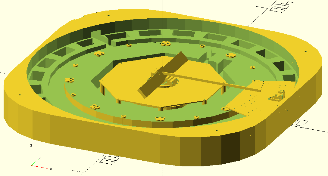
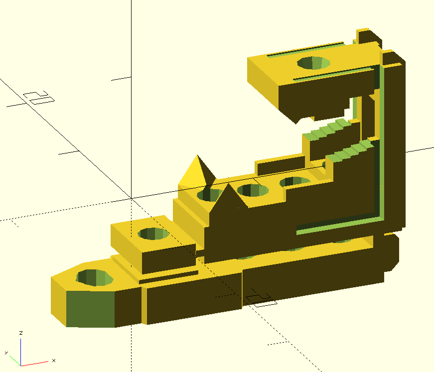
OpenSCAD rendering of the projector base design with two PCBs and one LD holder installed, along with the laser beam from LD to central mirror.
It was time to send off the circuit board and 3D print files to PCBWay for manufacturing. (The DipTrace files are available here and OpenSCAD files are available here.) For the optical encoder, I ordered a SMD stencil with a DXF file of the cutout shape (generated with OpenSCAD), and as before they correctly processed this unusual request without complications. This was the time of peak tariffs, so I actually ended up paying more in tariffs than the parts themselves cost, but I suppose thwarting creativity is the essence of business and politics. It would almost have been cheaper to book a flight to China and carry back the parts in a suitcase, but I did not want to risk getting questioned at either border, even though there is nothing illegal about transporting one's own hobby projects (yet). This extortionate scheme also meant that I did not order the LD holders from PCBWay, deciding instead to print them myself as I had done with the prototypes, which had the slight advantage of giving me more time to improve the design (and more confidence the design would work, since my files were fine-tuned at the 0.1 mm level for the particular printer and resin settings I had used in prototyping so far). The motor holder, which was made from laser-cut aluminum, could have been ordered from sendcutsend, however my past few experiences with them showed that they do not do a great job with deburring the edges of parts, and in one case bent the parts due to improper tab placement. I ordered the motor holder from PCBWay for the sake of comparison, and as expected the piece came back with all the outer and hole edges well deburred. The encoder ring holder was difficult to print without warping and was best suited for a powder process such as SLS, and this was the first time I got a reasonable quote price on xometry, so I ordered from them (I had attempted ordering from them as early as the ddr pad project, but it seems that for anything exceeding the size of a small trinket, the prices become astronomical - for instance the 44 cm projector base by itself would have cost more than the entire PCBWay order with tariffs included!).
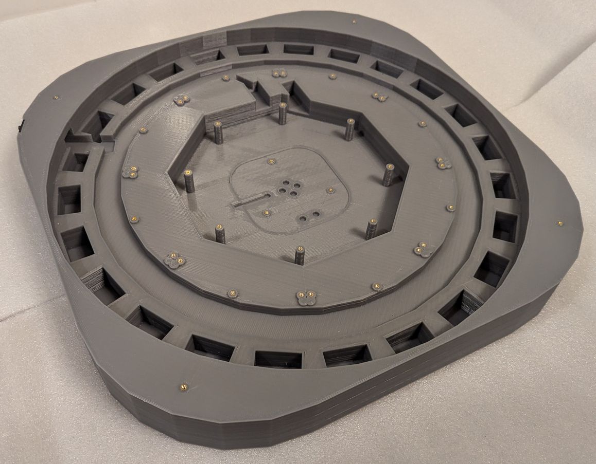
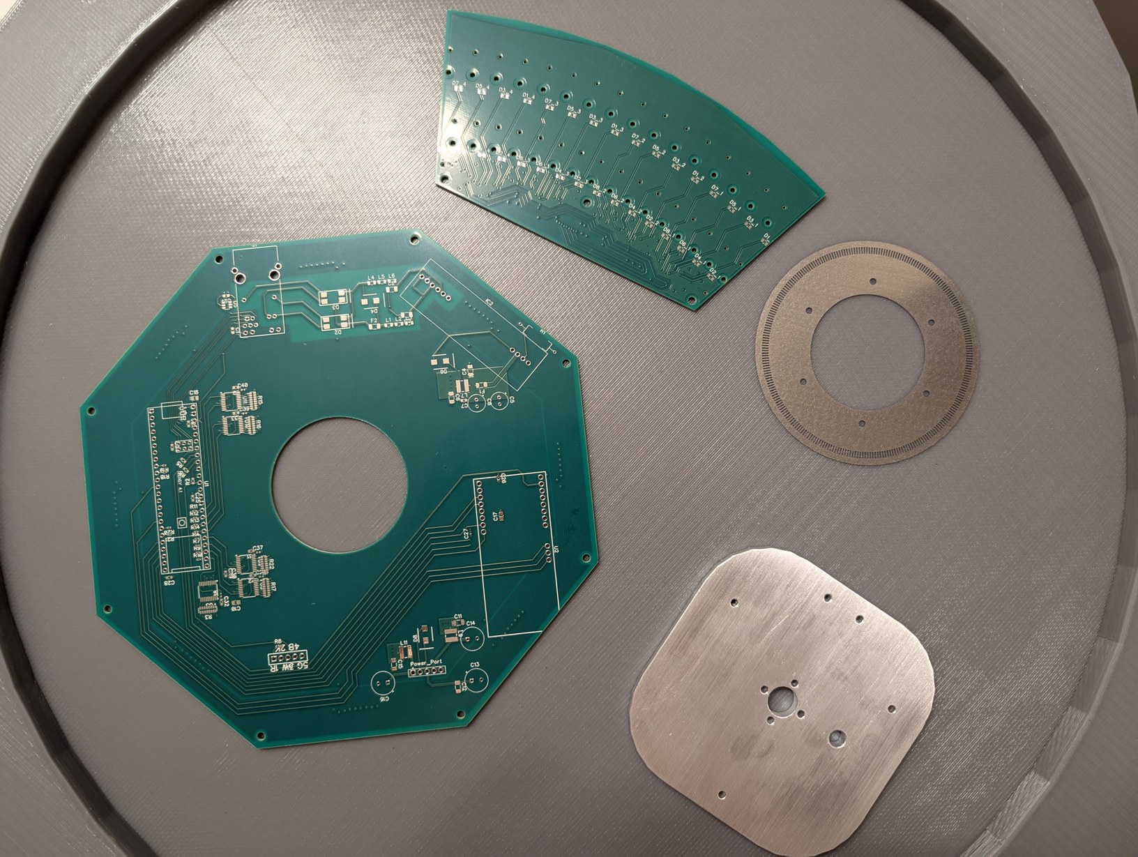
On left the 3D printed projector base, and on right the circuit boards, encoder ring, and motor mount on top of the projector lid.
The parts arrived and I was eager to test the mechanical assembly process. Everything fit as designed! Some of the LD boards were not fully level, but that would be a problem for later (I used 3 bolt holes on each board, to allow shim washers to be inserted to adjust the LD board angle). I completed the PCB soldering in about six hours, with the reduced number of components (in particular, the buffers, shift registers, and 8x parallel resistors) being a big help in achieving this. I used solder paste that was marked to expire in 2023 but which seemed to work not particularly different to when I first opened it (it may have become slightly less tacky and more prone to detaching from components during reflow, due to the flux being weakened over time, which caused a few IC pins to not be fully soldered). For the reflow, I used the same toaster oven technique as in the acoustic camera project. The detaching components were fixed manually with a soldering iron after visual inspection identified the affected pads. The through-hole components were also soldered manually.
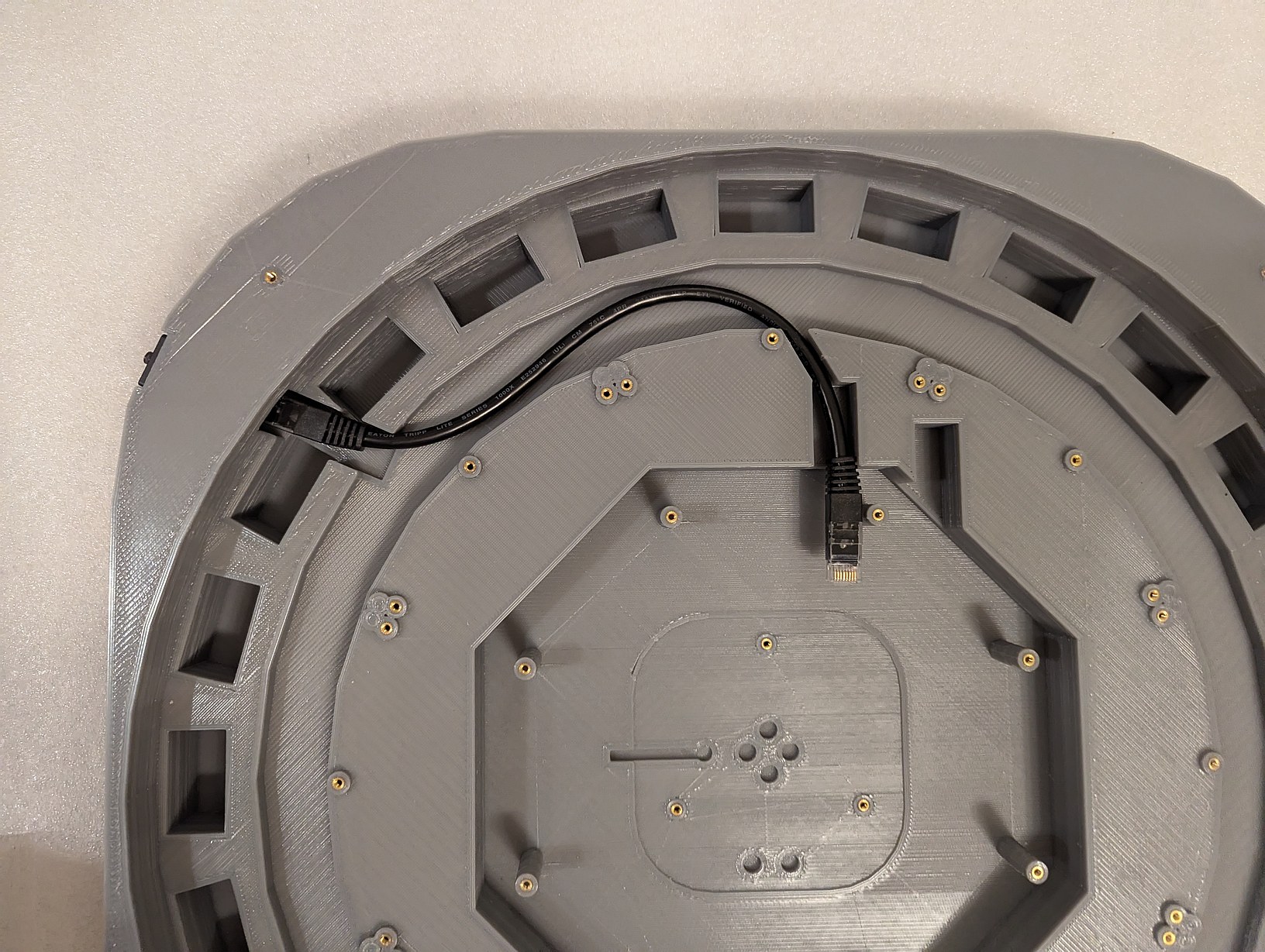
Testing the fit of the ethernet cable, motor holder, and PCBs inside the projector base. The wires coming from under the PCB are from the optical switch, and here I determined the length to which they can be trimmed to allow easy removal of the main PCB.
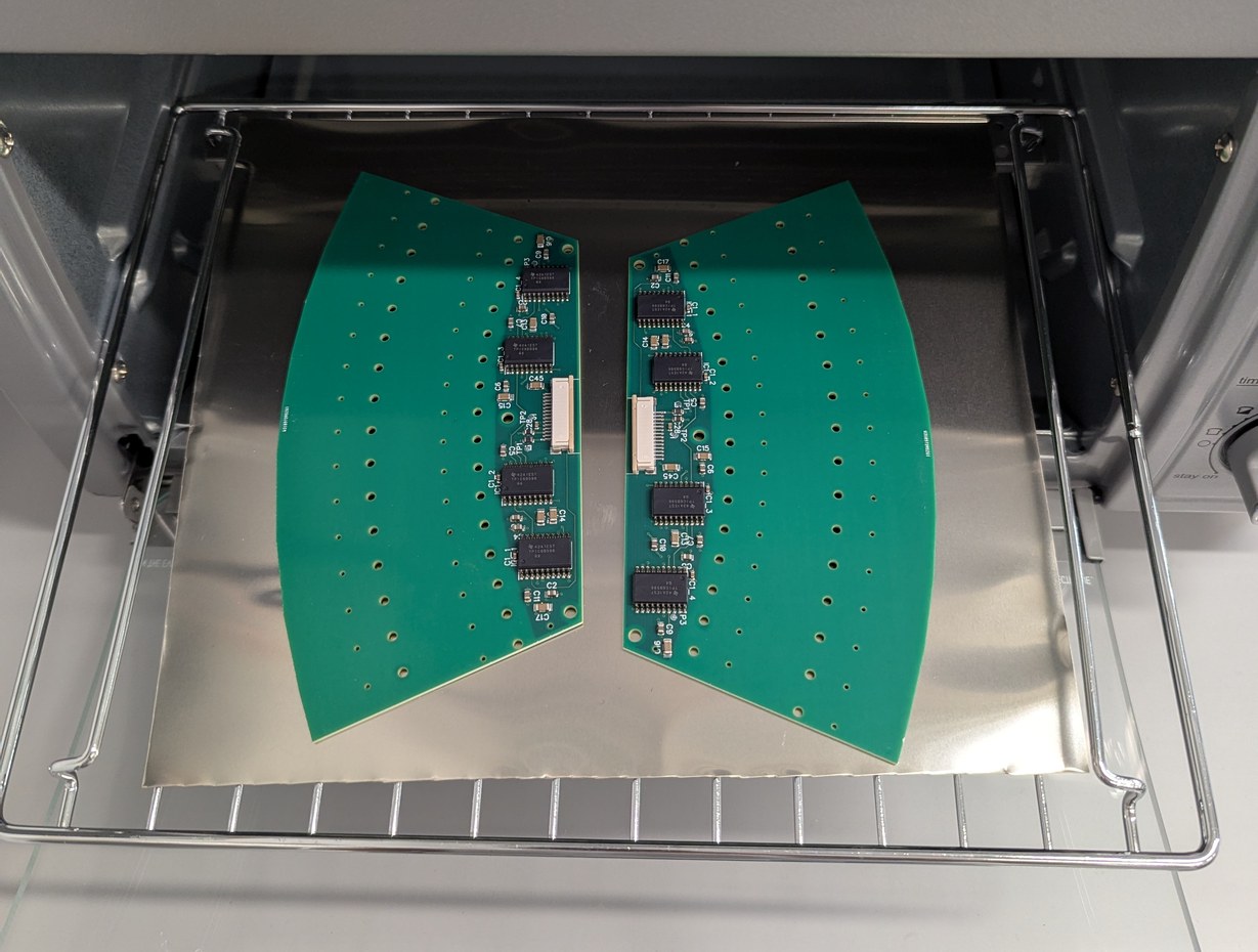
Soldering the LD boards in a toaster oven (a sheet metal cover is placed on top of the boards for even heating, the cover is removed for the photo), followed by optical inspection to identify bad solder joints for manual rework.
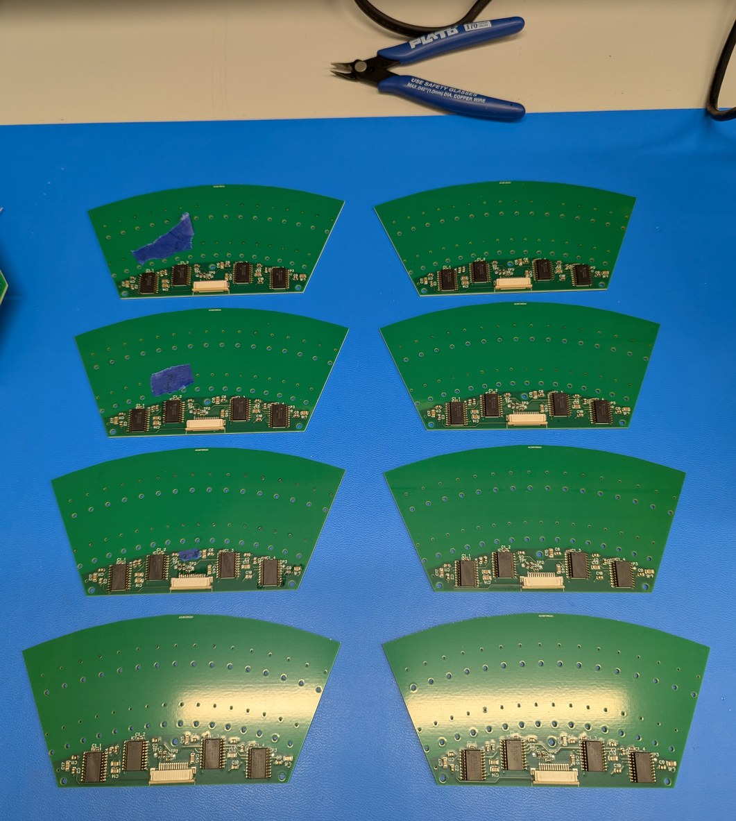
Manually soldering the through-hole components on main PCB and fixing bad connections on the LD PCB. On right, the main PCB after washing off the flux residue.
The motor spinning the mirror should rotate at a steady 30 Hz with minimal vibration. There is almost no load required to maintain this rotation (or so I thought). A good choice would be a small induction motor, such as used for precision gyroscopes, however I was not able to readily purchase one. Instead I use a brushless motor designed for a camera gimbal, which implies that it operates well at low speed (has a low "KV", or rotational speed per volt of input, rating). To drive this motor I considered two options - a no-name ESC (electric speed controller) from Amazon, or the TI MCF8316 which implements Field-Oriented Control. The ESC is clearly rated for higher power motors, and the MCF8316 is a single component that could fit nicely on a circuit board, so I thought it would be good for this application. I bought a "Brushless 33" module from MIKROE which contains this IC (for which I added headers on the main PCB), and spent over two weeks trying to get it to consistently run the motor. Supposedly this can automatically sense motor parameters using a routine, but when I tried running this routine it always failed. After manually measuring the motor resistance, inductance, and back-EMF, and entering those parameters, the routine would work about 10% of the time and give different answers for the P and I parameters of the speed loop. There were about 100 different parameters to go through to try and get something functional. Even after a bunch of tuning, the motor would start up maybe 10% of the time, of which 2/3 of the times there would be an anomalous high current draw with associated jittery noise, and occasionally the current draw would reach the limit of my power supply and shut down the chip. When it did run, the speed was audibly inconsistent (varying over 0.5 Hz at 30 Hz). I could get a consistent speed when the chip was running in open loop, but the setting meant to keep the chip in open loop also did not work in the way that would be usable for this project. Overall it was a very frustrating and unfruitful experience (and not for the first time - my attempts to get TI's FOC products working with the hoverboard and mc2 projects were similarly disappointing), and based on TI forum posts, I wasn't the only one with this experience (there is even a post specifically about difficulties with camera gimbal motors). There was little flexibility in motor choice at this point as I had sized every other part in the project around it, leading to a few stressful hours as I wondered whether all is lost. Then I connected the ESC to the motor and it just worked, no tuning or coding required. Furthermore, the current draw at load (2 mA to 3 mA) was half or less of the best case of the MCF8316 (6 mA to 7 mA), and the speed control was much more stable. It did not start up successfully every time, however in that case the motor stopped and this could be identified using the encoder seeing no transitions, whereas the MCF8316 would sometimes shake the motor continuously instead of spinning it (somehow falsely thinking it was in closed loop operation) which would not be easy to identify with the encoder. It also never drew a high current from the power supply. Overall the cheaper option here was easier and better, despite not being designed for this use case (one thing to note is that supposedly motors can be wound for trapezoidal or sinusoidal commutation, and possibly if this was a trapezoidal wound motor it would not work well with the sinusoidal FOC method, but this does not justify the difficulties encountered with getting the MCF8316 to do anything in a consistent manner). It would still be nice to drive the motor in open-loop mode at constant speed, but the approximately 0.05 Hz stability of the ESC near 30 Hz was sufficient for this project. While the Teensy has the capability to output constant frequency 3 phase PWM waveforms without much difficulty, I did not want this to turn into a motor controller project, so I chose to use the ESC.
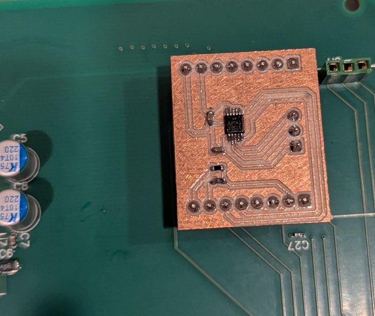
A further annoyance with this was that in hoping the FOC chip worked, I did not order a PCB for interfacing with the ESC, so I had to draw one up. This ESC used a potentiometer to output a voltage from 0 V to 5 V to set the motor speed. As the Teensy operates at 3.3 V there needs to be an interface between the two, and the DS3502 digitally programmable potentiometer, which allows a voltage up to 15 V on the potentiometer end with communication at 3.3 V, is a good fit. As this was a small board with a single IC, for expediency I thought to make it on a one-layer board using the small CNC mill at home. (Note that adafruit.com offers module boards with the DS3502, which I had on hand in case the custom milled board did not work; I still proceded with milling because I wanted the header pins to match the main PCB.) However I had not milled PCBs for a few years by this point and it took a while to refresh my skills. The DS3502 is a 0.5 mm pitch surface mount component, meaning the space between pads is 0.2 mm and trace width is 0.3 mm, which puts this towards the more difficult side of home-made PCBs. As I suspected, these tight tolerances caused much difficulty in fabrication. On the first attempt I milled the traces too deep with a V cutter, which made them too narrow. On two attempts there was a communication error that caused the CNC to stop mid-operation and lose alignment, so it was easier to start over with a fresh piece than to attempt re-aligning. On the fourth attempt I manually paused the CNC mill to check the depth of cut, which reset the machine coordinates. I thought, all this grbl stuff is not terribly resilient, once running it is better to not even look at the machine until it finishes, otherwise it will lose its coordinates. On the fifth attempt I used the depth values that worked properly on previous attempts and let the operation complete without stopping, and at the end found again that the traces were too deep. On the sixth attempt, I made many passes to gradually lower the depth to the correct level, to avoid cutting too deep. This was a slow process so eventually I thought it was deep enough and cut out the board outline. It turned out that in some spots the cut was not deep enough, so the copper traces were still connected to the surrounding copper plane. I tried to fix this by hand but it was impractical, as it was easy to cut through the traces while trying to cut them apart from the surrounding plane. Also during cutting the PCB outline, the end mill went about 1 mm deeper than programmed, which I thought was strange but did not investigate further. On the seventh attempt, I used the height map feature in Candle software, and manually set the heights of 4 points on the board. This was a key step for maintaining good isolation between traces, because the height of the PCB from left to right changed by 0.14 mm, which is more than the necessary depth of cut of about 0.05 mm. This uneven height was caused by clamping the PCB, and was the problem in earlier attempts. Again on the PCB outline step, the end mill traveled much deeper than programmed, and made terrible noise while cutting. I finally recognized that the spindle motor, held in a 3D printed component, was vibrating and sliding down during machining. The linear bearings also held in the 3D printed component were sliding out, resulting in a holder that was poorly supported holding a motor that was sliding about. Given this state, it was actually surprising the milling went as well as it did (I didn't break any tools, although I did slightly cut into the aluminum frame of the CNC when the end mill dropped by over 2 mm on the last pass).
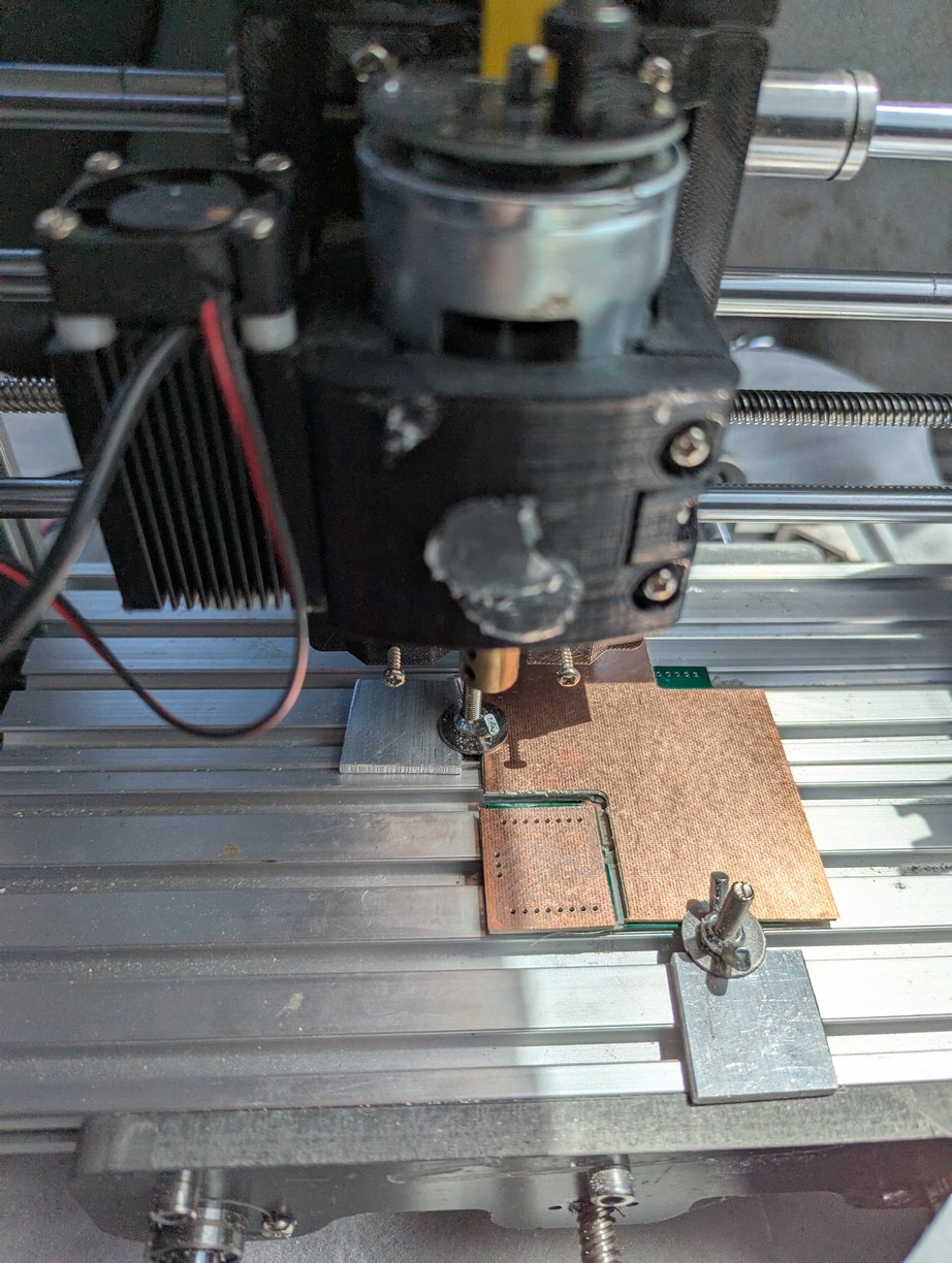
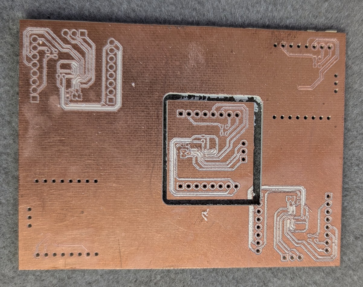
Photos of milling the PCB for digital potentiometer. In the first photo, on the upper right a linear bearing can be seen coming out of the 3D printed part, and the mill motor is dropping down inside its holder. In the second photo, a number of failed attempts at milling the board can be seen, along with the final part which was not great but functional.
The difficulties were not over yet (of course). Next I added flux and solder to the pads, then soldered the surface mount components careful to not bridge the tiny 0.2 mm gaps between traces. The absence of a soldermask makes this difficult. However even after soldering everything without bridging gaps, I could measure resistance between traces. This was due to the solder flux residue collecting in the milled grooves around the traces and providing a somewhat conductive path across the isolation barrier (I also encountered this in the touchpad controller project). Soldermask on a commercially made PCB means that often this effect can be ignored since most of the trace area is not exposed to the flux, however with the milled PCB this has to be taken into consideration, especially when there is a need to work with analog signals. Also the type of flux matters. The flux I used this time was paste from an old can and probably meant for plumbing rather than electronics, its residue was conductive and not water-soluble so presented more difficulty to remove. I soaked the PCB in a small container of flux cleaner for about 10 minutes, then wiped dry with a paper towel and confirmed isolation between traces with an ohmmeter. It took a few repetitions of these steps, each time the resistance slightly increasing, until above the 60 Mohm maximum of the ohmmeter, which I considered good enough. Finally I applied a conformal coating to insulate the board from potential shorting of traces by stray metal pieces. From the factory, the DS3502 defaults to a centered potentiometer wiper, which would cause the motor to start spinning at power-up, so before connecting to the ESC, the DS3502 non-volatile memory was programmed to start with a zero output. This way the ESC receives a low signal from power-up until programmed otherwise by the MCU.
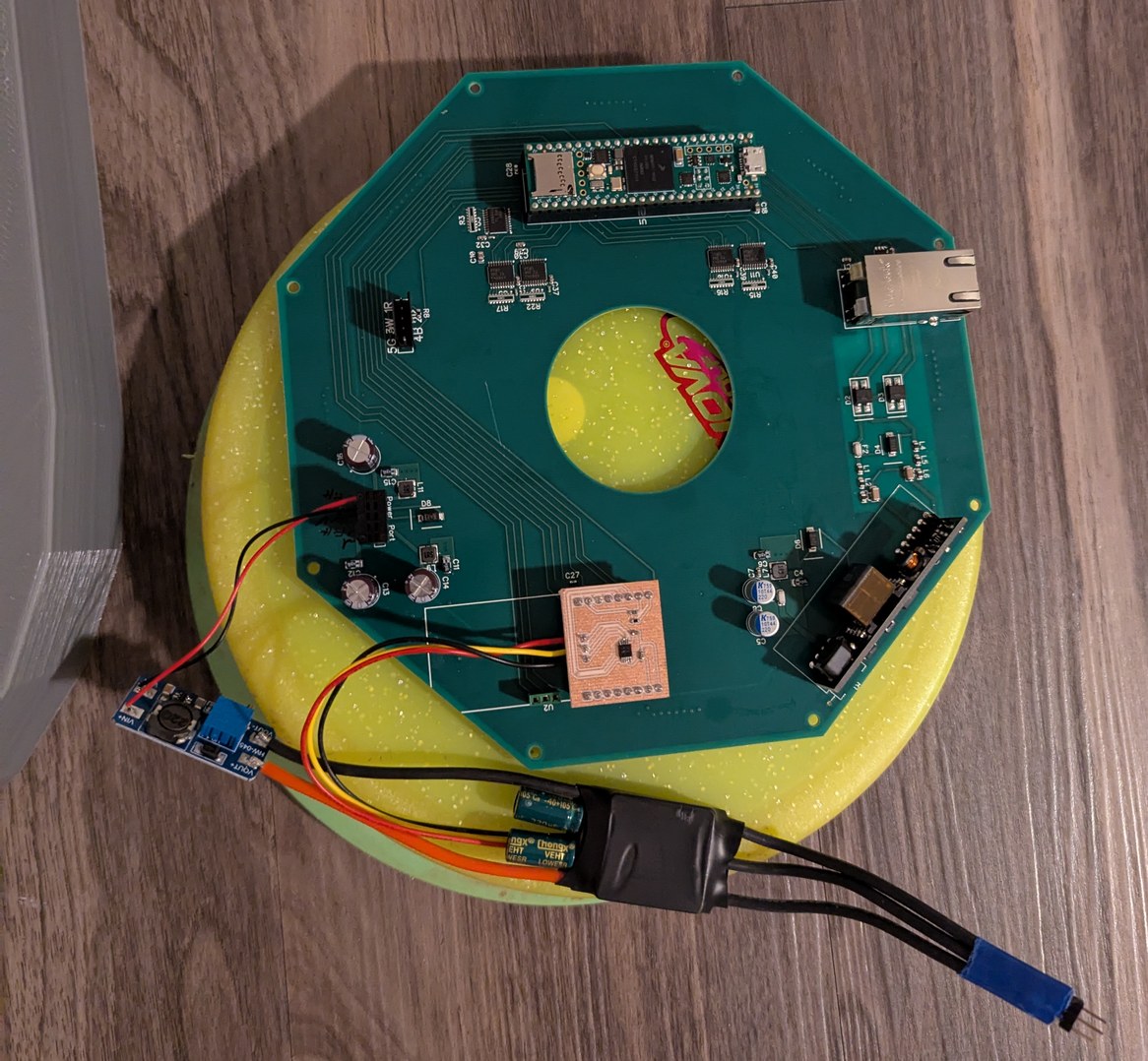
Installing the potentiometer board in the headers initially meant for the MIKROE board, and then connecting a no-name ESC to this board, powered through a boost converter module.
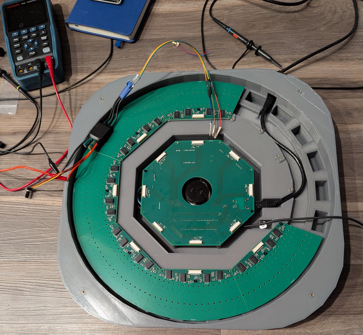
With the motor spinning up somewhat reliably, it was necessary to test the encoder ring, with the photointerrupter switch OPB931W51Z. The ring was designed with 256 cutouts (512 transitions light to dark and dark to light) spaced nominally at a 50/50 duty cycle but with one cutout set to 46/54 duty cycle to mark an index position. The index position needs to be known for an absolute angle determination, as only the lasers that are in front of the mirror should be powered on. Anticipating that there may be jitter in the optical switch timing, the optical transitions do not directly trigger the laser driver, but rather are used to capture a timer value which is then digitally processed and used to set the phase of the laser output timer. This proved to be a good choice not solely because of the jitter (which may have been acceptable) but because of the huge deviation between the mechanical and optical duty cycles. In fact during the first test, there were no transitions for about half of the disc's rotation, due to the tilt of the encoder ring holder (prototype that was 3D printed in PLA, as the one printed in resin became highly warped due to the use of 3 mm thick walls) causing the ring to move up and down within the optical switch opening over the course of a rotation. During the no-transition period the switch was reporting a transmissive state, meaning some light was received continuously by the sensor. I used the CNC mill to drill some holes in an old PCB to make a quick adjustable-height encoder ring holder using sets of nuts on M2.5 screws as adjustable standoffs, to hold the ring level. This holder did not meet the clearance requirements for installing the main board so I had the main board on even longer M2.5 screws used as spacers to hold it about 2 cm above its nominal position for the testing. Even when held level in the middle of the sensor, problems persisted unless I moved the ring towards the very top of the sensor opening, nearest to the small aperture of the sensor.
Connecting the encoder ring to the motor, I found the performance was not good due to the open regions of the ring being too close to each other. All 512 transitions per revolution could be seen if the encoder ring were moved up towards the top of the optical switch slot, but the ring holder was designed to hold the ring in the middle of the slot, about 2 mm lower. I thought I might make a quick version of a properly sized holder using a 3D pen (a hand-held version of the 3D printer hot end), but with the unsatisfying result I remembered why these pens aren't so popular.
Using an old PCB from another project, I made an adjustable encoder ring holder based on using M2.5 bolts as threaded studs, with the ring held between two nuts on each bolt, so either side could be adjusted up or down relative to the PCB, which was flush with the top of the motor. In this photo the installed location of the optical switch and encoder ring are more clearly visible.
Assuming that the part was machined to design specifications, the 50/50 mechanical coverage in the optical switch is converted to something like 85/15 optical coverage, with most of the time the optical sensor reporting clear transmission. This is one downside to using an optical switch with built-in IC, as the threshold is set by the factory, and in this case it seems that if any light made it to the sensor it would report a transmissive state, so a high value was seen when any part of the solid encoder ring was not fully overlapped with the sensor aperture. The sensor aperture was approximately 0.25 mm and the encoder solid width was approximately 0.47 mm, so a zero state was reported only for 0.22 mm out of 0.94 mm. There may have also been some contribution from light reflecting off the inner edges of the encoder ring cutouts, as the material was shiny stainless steel. The shortest period between transitions corresponded to 50 kHz data rate, which was below the 100 kHz claimed in the data sheet, so I suppose this is usable for timing, although it is pushing the data rate limits of the OPB931W51Z and it may be expected that significant filtering will be needed to get a clean speed and position signal. This complicates the identification of the index position, which relies on a 4% change in duty cycle between the transmissive and blocking states. Interestingly, the timing between consecutive light-to-dark or consecutive dark-to-light transitions was much more consistent than the time between adjacent light-to-dark and dark-to-light transitions. This is probably because with adjacent transitions the position-dependent differences between mechanical and optical duty cycle enter the equation, and with consecutive identical type transitions these differences cancel out. The GPT2 timer is used to record every transition (without further knowledge of which type it is), by using its input capture mode, so the timer value is captured in hardware at the moment the optical switch state changes, and then is read out by an interrupt which only has the restriction that it must complete before the next transition (for which it has about 10000 clock cycles of the 600 MHz CPU clock). Slower processing is done outside the interrupt using multiple values in a buffer. The timestamps of transitions are convolved with the filter [-1,0,2,0,-1] which identifies the duty cycle difference of the index position using only same-type optical transitions. At the index position, the convolution value is over 2 times the value for any other position, which makes the identification reliable. If the disk is rotating in reverse, there is a smaller peak which is about 1.5 times the value for any other position. This condition is identified by evaluating both minimum and maximum values, and confirming their relative sizes are as expected (otherwise a reverse rotation error is reported).
Next it is necessary to map the transition times to theta angles of the motor and mirror. If the mechanical and optical match were perfect, and the mechanical design matched the CAD file, this would be an easy task, but the optical transitions are not identical to the mechanical design and are dependent on encoder ring height in the sensor which may change over time. Thus the firmware should generate the map and update it dynamically (for instance if some components expand or contract due to temperature shifts). Then this map is used to identify the best estimate of current position, but in the presence of expected jitter of individual transition times. This is approached by a multi-layer averaging scheme, which updates the position map using speeds averaged over one revolution (which are mechanically guaranteed to be one revolution) and updates the current position using the mapped averages over the most recent transitions. It would be nice if there were a true constant speed motor driver to calibrate all these things, but with knowing rather little (512 transitions per revolution, spaced consistently throughout multiple revolutions even if not uniformly within each revolution, small changes in speed over one revolution, and a trustworthy clock) it is possible to eventually generate a usable output. The change in working encoder ring height from middle of switch to top of switch may have meant that the encoder ring holder would need to be redesigned after I had already sent the file for manufacture, but luckily this could be accomodated by placing the encoder ring on top of the holder surface rather than below the surface as originally planned, so I could use the same part.
I set up one laser diode in a prototype LD holder in a position on one of the LD boards, and connected this to the main board (after removing the encoder ring test jig, so everything could fit back into the case again). Looking back over the schematics I noticed one problem - the line buffers were not tolerant of voltage above Vcc on the input pins, and in the case where the Teensy was powered by USB and there was no PoE power, this could occur. Thus I added a simple resistive divider (onto the ESC interface board) which could be read by the Teensy to confirm PoE power is present before sending outputs to the buffers. Meanwhile I just had to remember not to operate in this state. But this was not the only problem, as the laser diode would not turn on, after programmatically toggling ("bit-banging") the lines at 500 kHz. The unthinkable had happened - the 14-pin connector signals on the main board and LD boards did not match up! This was made worse by the fact that I knew something like this could be a risk so I checked and even double-checked the connectors before ordering the boards, but in the intervening period I must have decided to change the signal order. It felt like the oracle's premonition - you can try to avoid it, but it will happen anyway! There was no way to fix this in software, as one of the affected pins carried the data for each LD board, which was wired differently from the clock and reset signals that were common to all LD boards. At least the ground and power pins matched up correctly (I triple-checked those) so I did not destroy all the circuitry. Having just soldered all 9 boards, I was not interested in repeating any of that work, so I sought to repair the fewest affected traces, with software pin re-assignments handling the rest. Unfortunately this meant that my carefully laid out, impedance-controlled(-ish) traces would be changed to EMI-radiating jumper wires, defeating the whole point of using 4-layer PCBs. There's no avoiding being humbled before the digital design gods.
Somehow the data connections got swapped between the main board and LD board.
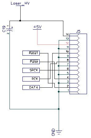
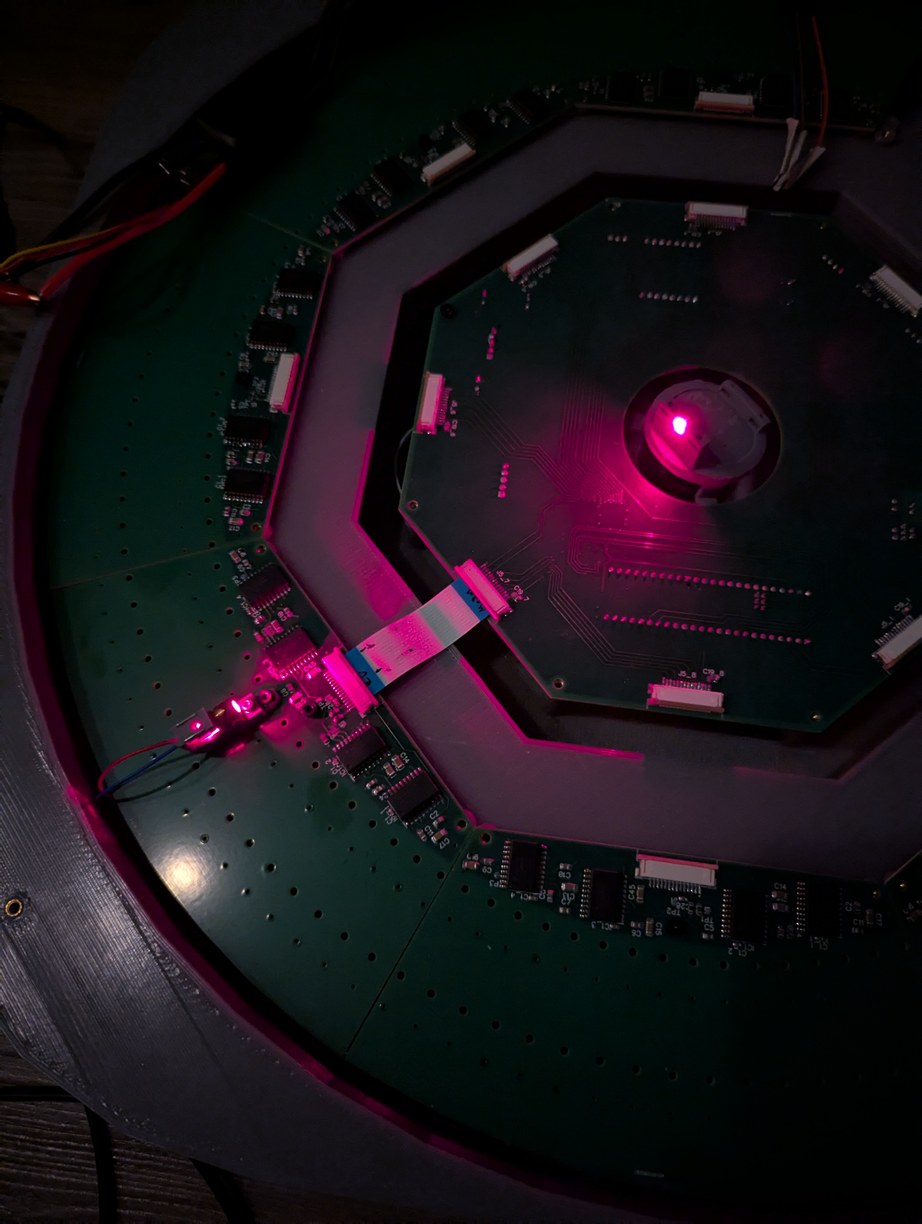
But I was anxious to get first light, and for the sake of expediency, I crossed the lines in the ribbon cable. This was the least risky option as I had bought extra cables, and breaking one does not affect the PCBs. This also allows me to hide the mistake under the cable so it is not visible once the projector is assembled. However, crossing there would involve a discontinuity in the return current; either the grounds would also have to be interconnected at that point, or the repair would have to be done over the solid ground plane of the main PCB (there was too little room on the LD PCBs for an effective repair). For the purpose of the test, though, the cable cross-over worked, and the laser diode still did not turn on. Reversing the order of shifted bits, recalling that the first bit that gets shifted out ends up at the last position of the last shift register, I finally achieved first light as the laser diode turned on with a bright red glow! The same could have been done by just connecting it to a power supply and pressing the "on" button, but still this felt like an accomplishment as the PCBs and firmware functioned as expected, and if it could turn on 1 LD, then it could turn on 256, and that would be quite a sight.
First light from an LD installed in the projector, confirming that the electronics work as expected. Two signal lines needed to be swapped in the ribbon cable connecting the main and LD boards. In these photos a resin 3D printed encoder ring holder prototype can be seen, but this part warped badly due to thick edges and was not subsequently used.
With the ESC and DS3502 connected to the main board, it was possible to spin up the motor. It reached the target 30 Hz with a bit over 13 V, requiring a boost converter connected to the main 5 V rail, for which I used a small MT3608 board bought on Amazon (I checked that when the 5 V input is turned off, the output of the board does not exceed the setpoint, but just in case I added a 15 V Zener diode to prevent over-voltage on the ESC). However the more I experimented with this configuration, the more I became concerned about the noise level. The gimbal motor was not intended to be used in this manner, and when spinning at 30 Hz the bearings made annoying vibrating, clicking, and bouncing noises. With so much noise, it would be difficult to concentrate on the faint projected points when the device is in operation, and it would detract from its performance. Thus again I found myself in a tricky situation. If only there was a motor that could be guaranteed to be silent and was designed for the 30 Hz speed range at low load... A brushless motor such as used for drones or drills is not a good choice, because it is intended for higher speeds and higher powers, and makes lots of noise due to the bearings used. After some pondering, I found that a PC cooling fan motor would be a good choice. These fans spin at about 1800 RPM, have relatively low torque requirements, and are designed for quiet operation. Even better, they have a built-in controller so I don't have to deal with those complications again.
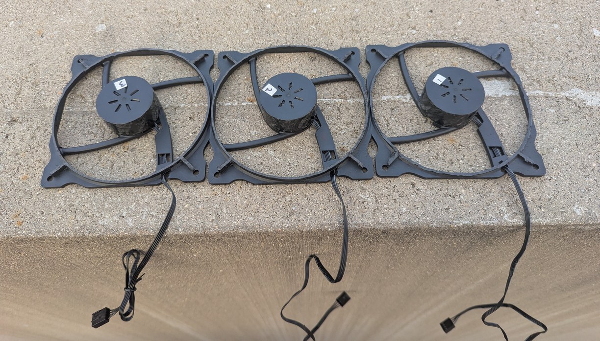
The only challenge is that I could not find any way to buy the motor without the fan. Thus I bought a set of five 120 mm fans (so I would have extras in case my first few modification attempts failed) and then used a rotary tool to cut off the blades from the hub (that's a real bladeless fan, unlike the Dyson advertisements). I also cut the outer case shorter vertically so it would fit within the constraints of the existing 3D printed box and PCBs. For this I used a 2 mm PCB endmill in the hand-held rotary tool; it took some practice to learn the right amount of force to apply and in which direction to apply it (since the tool tends to move laterally to the desired cut direction), but by my third attempt I felt fairly confident in the blade removal procedure. After the 2 mm endmill, I used a sandpaper bit to clean up the surface to minimize imbalance of the hub. Next I used a marker and a piece of tape to locate the center of the fan hub while it was spinning, and then used the center point to visually align the hub to the coordinate system of the desktop CNC mill (I expect this procedure to be accurate within 0.5 mm, and maybe as low as 0.1 mm). Then I used the CNC mill to drill holes spaced symmetrically about the center point, using painters tape to keep the hub from rotating during the operation. I planned the machining operations such that they would not require removing the hub from the fan base. This is because machining generates lots of plastic chips and dust, and I did not want these to end up in the fluid used for the hydrostatic bearing of the fan. In between the machining steps, I vacuumed the plastic chips that became stuck inside the hub. Also while it is possible to remove the hub by pulling on it with sufficient force, I was not sure whether the fan was designed to be pulled apart in this way (with another fan I have pulled it out and re-inserted it multiple times with no apparent ill effect, though it is likely some dust got into the bearing fluid), and so preferred to keep it in one piece. Finally I drilled 2 mm holes on top of the hub for improved air circulation so that the motor windings would not heat up as much. The modifications worked surprisingly well, and the motor was spinning very quietly at the target speed with minimal power consumption.
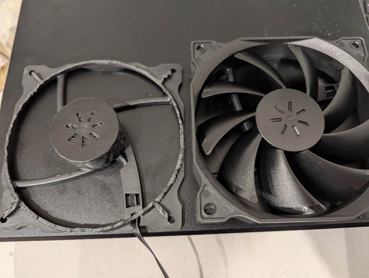
On left, a comparison of a 12 V PC fan, after and before removing the blades and half of the outer case with a hand-held rotary tool (along with adding ventilation holes for the stator). On right, this process is repeated 3 times to have extra motors to work with in case some of them get broken in future steps.
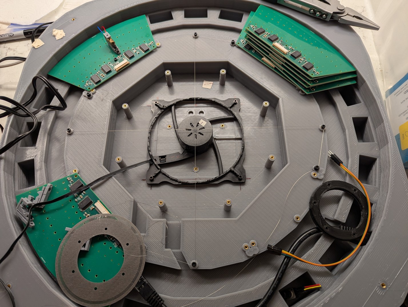
Since the projector base was not originally intended for this motor, it was necessary to insert new melt-in nuts in the correct locations. To find these locations, the motor was centered using thin intersecting wires referenced to PCB attachment points that are intended to be perpendicular.
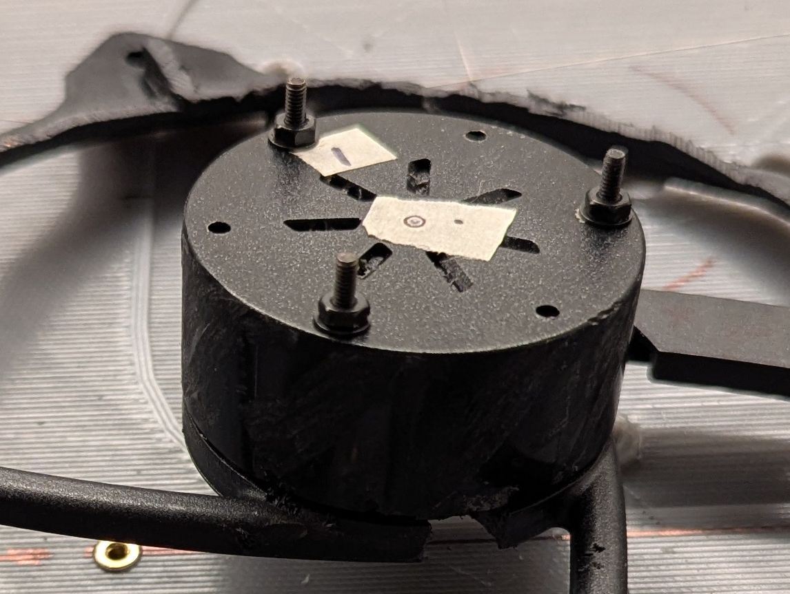
The center of the rotor is found and then 6 holes are drilled at the outside of the rotor. M2 bolts are inserted from the bottom, through a small slot cut under the rotor (seen towards the bottom of the photo), and then a nut is placed on top and tightened, after which the threaded section coming out of the rotor can be used for attaching the encoder ring and mirror.
With this encouraging result, the use of a PC fan seemed like the right choice, despite the extra work involved. And speaking of extra work, it was time to re-design the main PCB, since there were too many changes that were being made if the fan was to be added. Already the swapped data wires were annoying, now a new connector would need to be added somehow to control fan power and PWM (this fan model did not go to zero rotation at zero PWM, therefore an extra power switch would need to be added to allow the motor to be fully off), and I was increasingly concerned that there would be excessive mirror vibration if I was not able to balance the spinning assembly. To balance it accurately, an accelerometer should be added along with a holder that would allow some deflection of the motor base. The holder is conveniently already part of the fan assembly, but the accelerometer requires adding a new connector to the PCB. Further, if making all these changes, it would be worthwhile to modify the encoder ring design to address the duty cycle issue above, because in its present state the signal becomes unusable if the ring's vertical position in the optical switch is lower than about 70 % of the slot opening, which might happen occasionally from temperature changes or vibration. Overall the amount of "quick fixes" seemed to be adding up so it was worth ordering another board design. In turn, if I am getting a new PCB, it is worth trying to improve a few things from the first version. Specifically, I changed the pins used on the Teensy board so that the LD output used FlexIO2 and optical switch input used QuadTimer3, both of which support DMA request signaling. This would hopefully allow even less time to be spent on interrupts, which would be a key step to speeding up the data output so as to allow different brightness levels (based on total time a pixel stays on per frame).
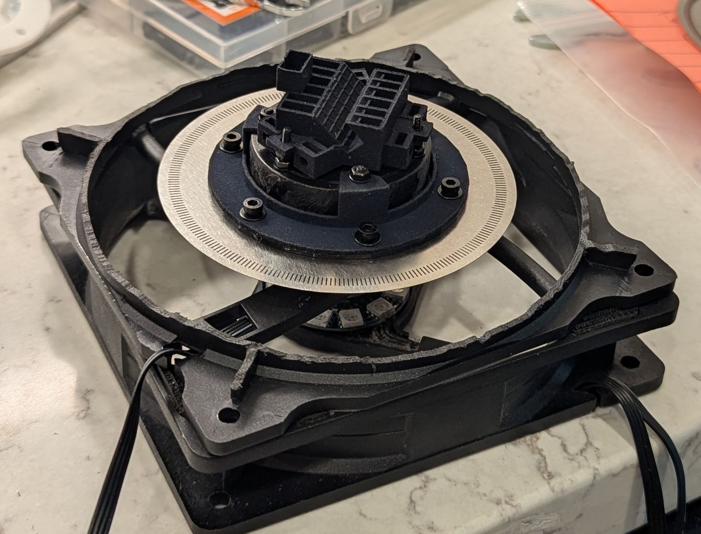
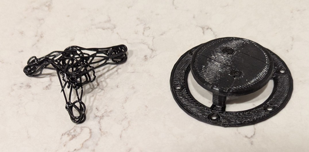
A demonstration of the assembly of the updated encoder ring holder, ring, and mirror holder attached to the PC fan rotor. The ring has smaller cutouts to improve the optical switch duty cycle. The holders are 3D printed nylon parts ordered through xometry, with much flatter contacting surfaces than achieved by my PLA printer. The assembly is on top of an old PC fan that was taken apart to check whether the internal bearing still works after removing the rotor (it does).
If I am putting in this much effort to optimize the timing of the firmware, I thought I may as well take a look at the default configuration that the Teensyduino implementation leaves me in when it calls the loop() function. Overall there are many good choices that leave almost all peripherals available for custom configuration, however I could not understand the way delay functions based on millisecond and microsecond timers were set up, and I was rather concerned about how EventResponder operated (based on forum posts on pjrc.com I haven't been the only one). The 100 kHz SYSTICK clock was set up to generate interrupts at 1 kHz to increment a millisecond timer variable. With EventResponder enabled, this would call the EventResponder routine which would disable all interrupts while it checked whether a request was pending. The jitter from disabling interrupts at 1 kHz is concerning. From what I can tell, at least the code was written in such a way that if nobody registered an EventResponder event, the interrupt-disabling routine would not get called, and the timer interrupt only took two instructions. However I could also see no need to have 1 kHz interrupts to increment a counter. The SYSTICK timer already does something analogous in hardware (it counts down rather than up). The interrupt allows synchronization of the millis and micros counters to the CPU cycles counter, but does any library actually need that? It felt like maybe one of the authors at some point wanted to build a real-time operating system, and remnants of that code were still defining how the timers were used, without much justification.
So I eliminated the 1 kHz interrupt and commented out most of EventResponder. Both millis() and micros() were redefined to work by reading the SYSTICK timer and incrementing an intermediate counter, which extends the 24-bit timer to 32-bit milliseconds values, thus behaving identical to the original millis() as long as one of these functions is called at least once in 167 seconds. The micros() resolution is worsened as each SYST_CVR interval is 10 microseconds long. A challenge with using multiple counters like this is that the function calls are not safe to use in interrupts (the functions could be written to be thread-safe, but interrupt code should not be using delays in the first place). Microsecond timing resolution and thread safety is maintained in elapsedMicros (and could be in elapsedMillis) by direct reference to the counters ARM_DWT_CYCCNT and SYST_CVR. This would change the behavior of elapsedMicros and elapsedMillis, since originally they used micros() and millis() respectively, which means that elapsed times would be rounded up like ceil(t) (assuming the object was initialized just before the next micro or millisecond, it would show one unit elapsed only a few CPU cycles later). The delay() function was originally implemented using micros() such that a 1 ms delay would be accurate to a few microseconds, and this approach has been maintained (but now with 10 microsecond resolution). In the updated implementation elapsedMicros is rounded down by 1/600 microsecond (at 600 MHz CPU clock). However in this implementation elapsedMillis is limited to 167 seconds, which does not seem like it should be a big problem (for longer intervals, millis() or better yet the Real-Time Clock module should be used).
After implementing the above, it was necessary to modify the usb.c, usb_serial.c, and usb_serial.h files establishing the serial link over USB. These files directly use systick_millis_count and expect that the 1 kHz interrupt will update it regularly. Since this variable is now only updated on calling millis(), and millis() is no longer safe for use in interrupts, I changed these instances to use SYST_CVR instead. Then I changed the startup code to not enable the SYSTICK timer interrupt, and this change caused stalling at startup. Adding in a 1 ms delay (which is probably excessive) in the startup sequence fixed this somehow, so I had a working codebase without a 1 kHz secret interrupt potentially causing timing jitter. I also added a function to turn off the Ethernet jack LED, with a slight modification of the mdio_write() call in the QNEthernet library driver.
I wrote a quick test code that would capture optical switch edges on pin 15 to QTimer3.3 input pin, and then QTimer3.0 would be used to capture its counted value on an optical pulse and to output a pulse on compare with a compare register. The timer output would be connected via XBAR1 to the external trigger input of FlexIO2. This was another advantage in choosing FlexIO2 rather than FlexIO3 in the revised main PCB, as this meant the data output trigger signal could be connected without any external jumpers. On counting 512 optical edges in an interrupt, a constant offset would be set in the compare register, thus flashing on the laser diode at a fixed angle relative to the rotating mirror on every rotation. This worked previously with GPT2, and now I was trying to port it over to QTimer3. At first I could not receive the optical switch signals. It turned out that to connect the pin to the input required not only IOMUXC_SW_MUX_CTL_PAD_GPIO_AD_B1_03=0x01 and IOMUXC_QTIMER3_TIMER3_SELECT_INPUT=1 but also IOMUXC_SW_MUX_CTL_PAD_GPIO_AD_B1_03|=0x10, the latter forcing the pin to be treated as an input for the QTimer3 module (as it can designate the same pin as input or output, but perhaps this doesn't pass across the daisy chain register; in this case the pin would always be configured as output unless forced to be input). Having done all this, I got a very jittery and flickering output. The interrupt routine was rather long, and called at about 15 kHz, but I did not think it was long enough to cause missed interrupts. I confirmed this with a digitalWriteFast(1,HIGH) at beginning of interrupt and digitalWriteFast(1,LOW) at end of interrupt, as well as a digitalToggleFast(0) which would be easier to see on an oscilloscope. This showed that the interrupt ended well within 1 microsecond, leaving plenty of time before the next interrupt call about 70 microseconds later. After a few more days of testing I came to the conclusion that the QTimer module was not intended to function with both an input edge capture interrupt and a counter compare interrupt. When both of these happened at the same time, only the input edge capture interrupt would activate, and the input edge capture would be completely missed. Since QTimer has 4 timers, I separated the functionality so that QTimer3.3 would have the input edge capture interrupt, and QTimer3.0 would have the counter compare interrupt. The two are kept synchronized by setting both to the same clock and starting both simultaneously from zero. This functioned consistenly and gave a stable laser line segment projected on a wall. This static-delay scheme benefited greatly from the stability of the PC fan motor speed, and suggested that there is no need to track all 512 transition edges for feedback control, even 1 edge per revolution would be enough. However there was a need to implement speed detection and synchronization of the output data to the motor, so that a consistent "pixel basis" can be established.
While the encoder for the optical switch is divided into nominally 256 equal sections (one is purposefully smaller by a few percent to act as an index position), it is not advisable to use this to trigger the laser data output, because mechanical imperfections in mounting the encoder (in terms of tilt and center) as well as non-idealities in optical switch response depending on where the encoder disk is relative to the switch, means that the measured electrical edges from the optical switch are not equally distributed around the circle. Instead the following approach is used, which relies on the notion that after passing through 256 sections (=512 edges) a full circle has been completed unambiguously.
[-1,2,-1]; this is sensitive to the one section of the encoder ring that is slightly shorter than others, and this position is considered theta=0N and N-512 is found, and this corresponds to the time of 1 revolution, therefore giving angular velocity omega. This velocity is then multiplied by the time difference between optical edges N-256 and N-255 (approximately in the middle of the circle in consideration), giving an estimated value of the real angular difference between the corresponding transitionsNote the use of 2 timers: one captures the counter value at each optical edge, and another toggles its output to trigger laser data at a moment when the counter value matches a programatically defined target. This enables the input and output edges to happen on separate timescales, however it requires synchronizing the two sides, in such a manner that one does not have to happen strictly after another. This is done by splitting the calculation into two parts. After an input edge is captured, a best estimate for theta and omega at the moment of counter = capture value is calculated. This information, along with the capture value, is packed into a 32 bit sync variable, which is accessed atomically so does not require the use of more complex data synchronization techniques. Then after an output compare occurs, the latest value of the sync variable is used to calculate how far in the future the next compare event should occur, based on what the output target theta is. This makes for a natural division between the mechanical theta basis of the encoder, and the abstractly divided pixel basis of the laser diode data. Implementing this took another day of troubleshooting due to a missed signed subtraction operation: the QTimer counters are 16 bits, and the difference between two timestamps is found by subtracting two uint16_t types and storing into another uint16_t type. This is actually more effort for a 32-bit processor compared to uint32_t types, but ensures that roll-over is properly accounted for (that is, the subtraction 110-100=10 is same as 4-65530=10). I incorrectly assigned the result to a uint32_t type, which caused something like 4-65530=4294901770, as the compiler automatically assumed I needed the higher bit count value. With this fixed, the scheme worked successfully, keeping the position of the output laser beam steady on a location on the wall, despite changes in omega from 20 Hz to 30 Hz. The width of the projected laser line segment became longer at faster speeds, because I had not yet accounted for pulse width, however the start of the line segment was consistent, except for a small speed-dependent offset due to the few microseconds of data shift time between output trigger and data latch which were not accounted for in the feedback loop.
With the above ready, I attempted to reduce the rate at which the interrupt gets called, because firstly there was no need to update the theta estimator 512 times per revolution as the angular velocity of the motor was very stable (well within 0.1 Hz), and secondly I wanted to implement multiple brightness steps (or at least to have the possibility to do so later). For the latter case, DMA would need to be used as new data would have to be sent out every few microseconds, and this in turn requires smarter handling of the input than simply interrupting at every edge capture. I defined a "reduced theta basis", which is still linked to the mechanical rotor position but has 16 instead of 512 transitions. The 16 transitions are generated by using QTimer3.2 to divide the input edges by a factor of 32 (of which one factor of 2 is due to the change between a rising edge only trigger and a rising + falling edge optical transition). The divided output is then sent to QTimer3.3 for input edge capture. By everything I could find in the i.MX RT1060 reference manual, this should have worked, but it again didn't. After a bit more head-scratching where the best guess I could make was that the QTimer module on occasion uses the compare preload registers even when I request no compare preload, I just assigned the same value to both the compare register and its preload register, and furthermore used another XBAR1 channel to connect one timer's output to the next timer's input (the manual suggests that the timer pins can be used as input and output internal to the module, but this does not work when using the output of one timer to capture an edge on another, as far as I can make out), I finally had a working code. Anticipating the multiple brightness steps, I set up the FlexIO2 module to output a reset pulse based on a timer, which itself could be reset if it was triggered before it reached its compare event, thereby extending the laser output period until no new data had been written out for a set time. This means that a few fast bursts of data can be used for brightness steps, followed by a period of no data which would automatically cause the laser shift registers to reset (so there is no need to output zero-filled data to turn off the lasers).
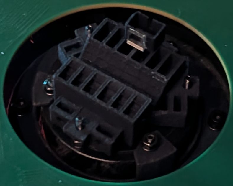
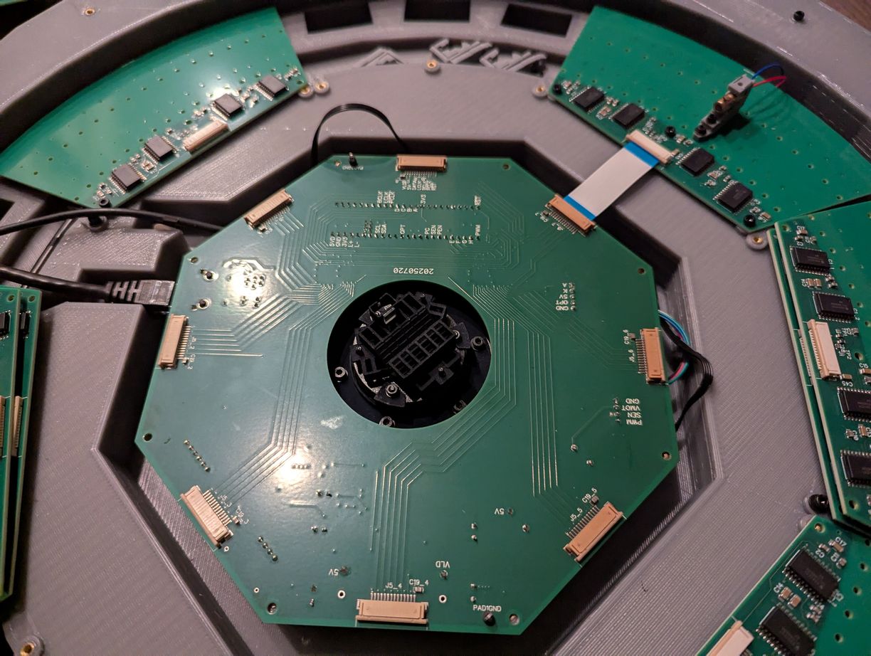
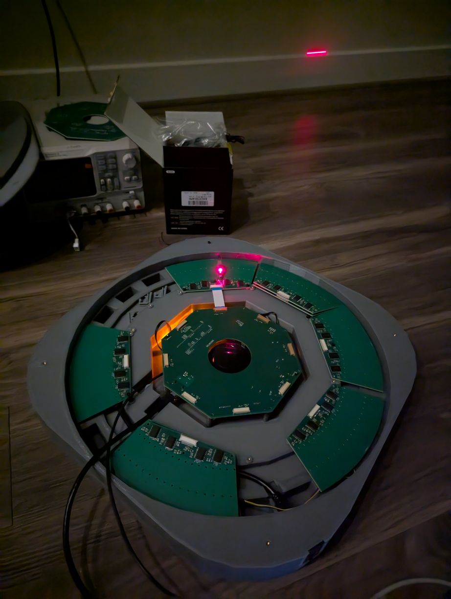
Setup for testing rotor and laser synchronization, by using one small (5 mm wide) mirror glued in the mirror holder and one LD that was set up previously. When synchronized, the projector successfully outputs a line at a fixed angle on the wall with the mirror spinning.
Now it was necessary to return to the tilted mirror reflection calculations from above to better define the mapping between the pixel basis and individual laser diode turn-on times. It eventually reduced to the following code (scilab script), where (r,c) are the input row and column in angular basis phi and theta, while (l,m) are the output laser number and mirror step in theta relative to the index position, both using modular arithmetic.
if((r+c)%2==0){
	l=(numlasers/4)-(r-c)/2;
	m=(numlasers+1)+2*(c);
}else{
	l=(r+c+1)/2-(numlasers/4);
	m=(1-numlasers)+2*(c);
}
Each laser can be active for up to 180 degrees of the mirror's revolution, from the time of the mirror normal being perpendicular to the laser beam on one side, then spinning around to be perpendicular on the other side. Subsequently the mirror is facing away from the laser and is not usable for projection by that laser (however it is used by the lasers on the opposite side of the device). The if() evaluation above determines whether the given pixel is on the "ascending" or "descending" path of the laser reflection, and then assigns a specific laser and mirror angle correspondingly. Neighboring pixels may have quite different lasers and mirror angles associated with them. However the number of mirror angles is fixed and uniformly distributed for all lasers, so by synchronizing the data output to the mechanical measurement of the mirror, we simultaneously pulse all lasers that are requested to be on for a given angle.
As the new board had a connector for an accelerometer, I used that to measure vibrations due to imbalance of the rotor. At 400 kHz I2C speed, and 400 Hz output data rate for the ADXL345 accelerometer, the program would poll the device regularly to find when new data was available (as the 4-pin "Qwiic" connector did not leave space for a direct interrupt line). When that was the case, the program would pull the latest synchronization data from the mirror theta observer, and store the accelerometer reading into one of 16 array spots corresponding to the nearest rotor angle at the acquisition moment. Encouragingly, there were no missed samples or synchronization errors with this scheme. Each array spot was a linear vector average, and there was no expectation of synchronization between the accelerometer data rate and motor speed, so over many revolutions the array would get filled out with a mostly uniform number of samples in each spot. Then it is possible to fit a sine wave to the Z component of the array (as this was most sensitive to vibration of the rotor, since the other two axes are aligned with the lateral elements of the stator which are relatively stiff) and find the magnitude of vibration as well as which mechanical angle to use for adjustment. The results of this measurement were more speed-dependent than I anticipated: at lower rates of revolution such as 10 Hz the vibration from a 2 g*mm imbalance (two M2 nuts added on one side of rotor) was below the sensor noise (about 4 mg where the g here refers to gravitational acceleration rather than mass), at 20 Hz there was some sort of resonance so the single period sine wave was effectively zero but there was clear periodic vibration at a multiple of the revolution speed, and at 50 Hz there was a clear single period of oscillation. I had hoped to adjust the mirror to below 1 g*mm, which seems like it would require using higher speeds than the 30 Hz I originally planned for, so maybe I won't adjust out all of the imbalance. I also implemented an overall AC RMS measurement, which gives vibration magnitude but not direction of adjustment, and perhaps with some trial and error this could be used to improve balance even when there is not a clear sinusoidal trend.
With the need to further add ethernet connectivity and EEPROM storage, my usual approach of using one huge .ino code file (exceeding 100000 bytes) was becoming unmanageable. Then I read about how the Arduino IDE actually works, and that multiple .ino files can be placed in the sketch folder, in which case the IDE will concatenate them into a single huge file behind the scenes - just what I was looking for! (To clarify, this is because I really don't enjoy dealing with .h files.) So I have, for the first time, split up the code into multiple .ino files, which helped more readily access functions that I needed to change during development. Although I wish the IDE would also automatically identify all the global variables; as it does not, those are moved to the top of the main file. The firmware code files are available here.
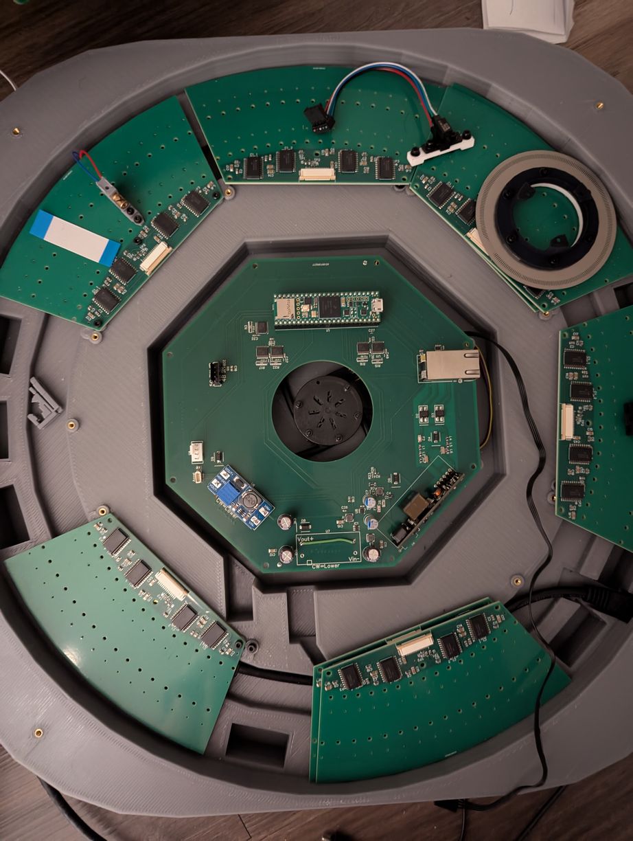
Laying out the different components in the projector base, before beginning assembly of the LD boards.
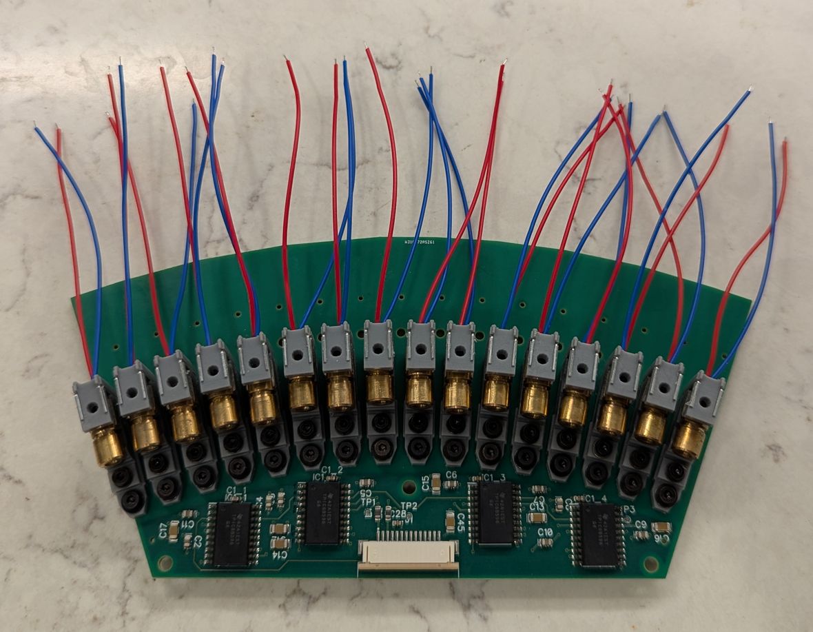
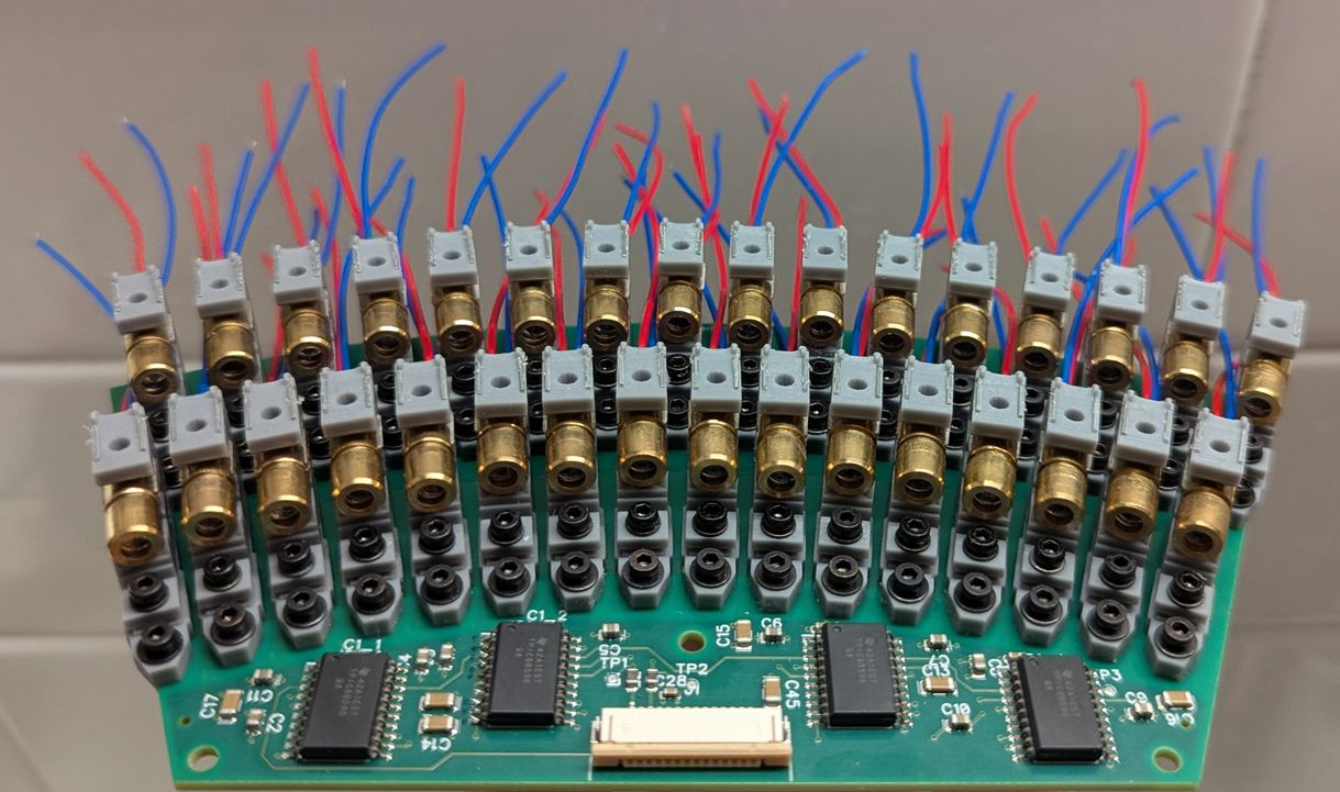
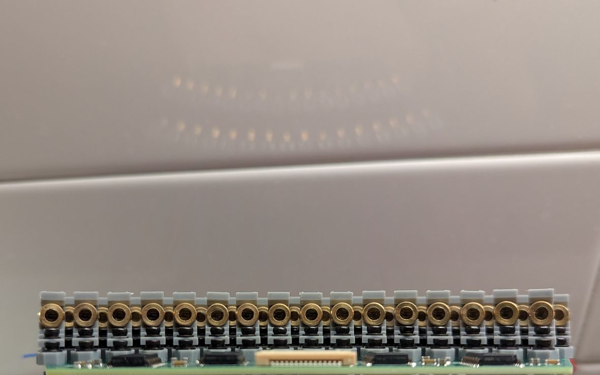
Placing the first 16, then 32 LDs on the LD PCB. On right, the view of the LDs from approximately the virtual center point, illustrating how the gaps between inner arc LDs are sized to just allow the laser beams from the outer arc LDs to pass through. In this way laser beam density is maximized given the 6 mm LD package.
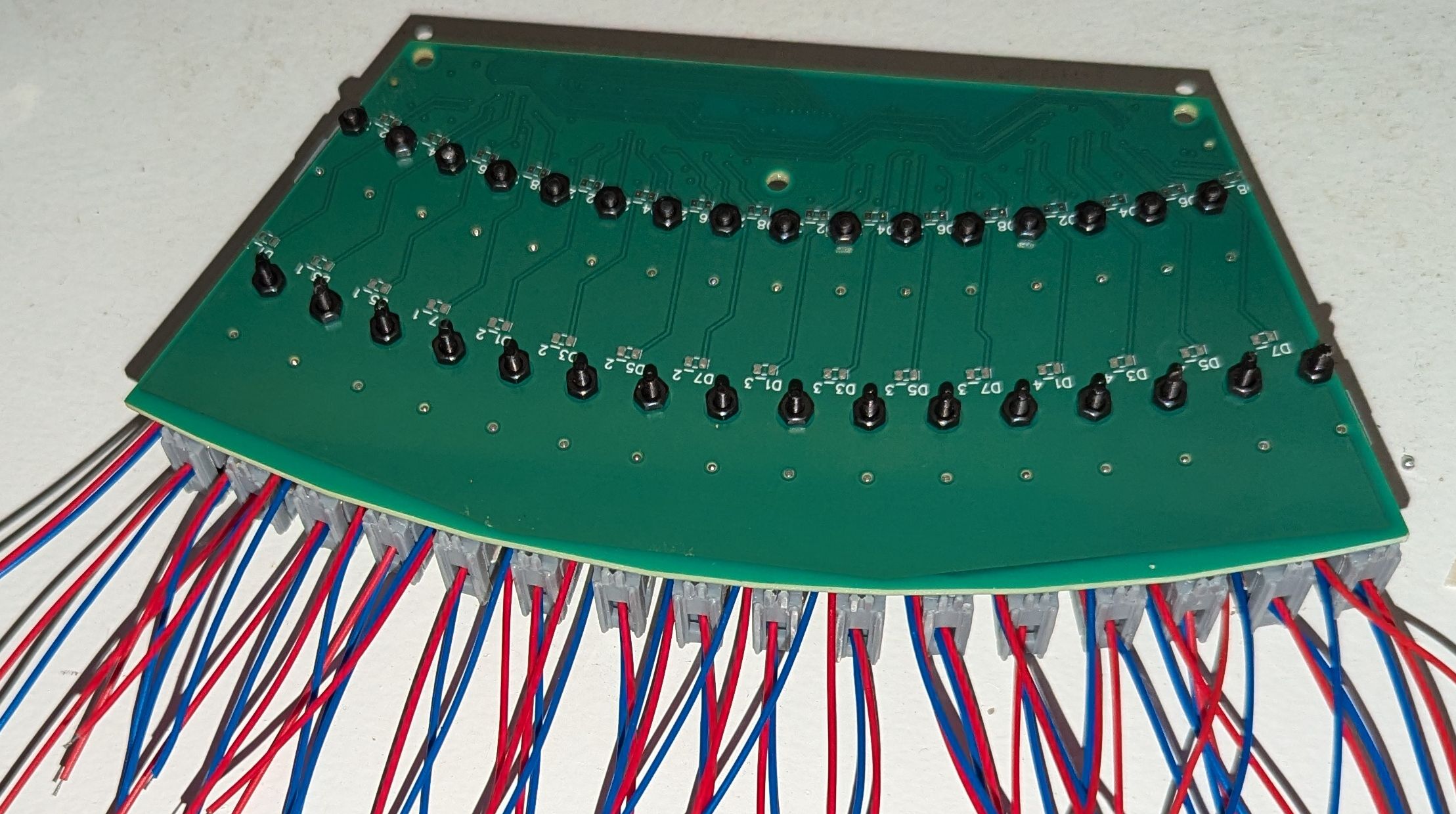
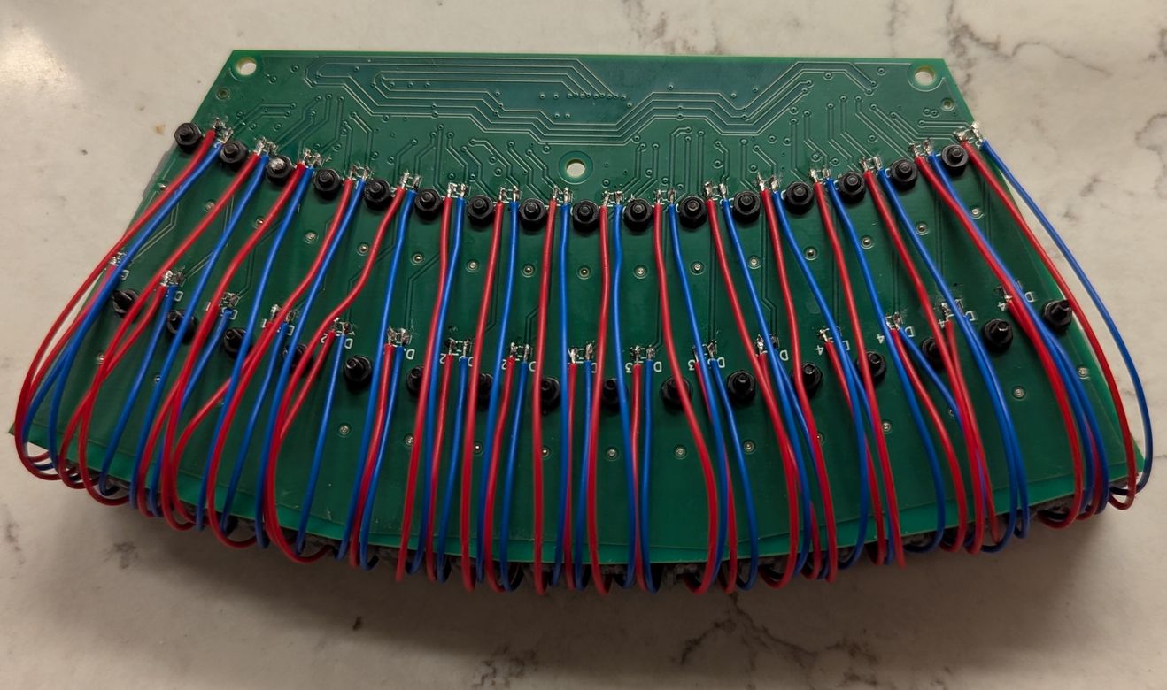
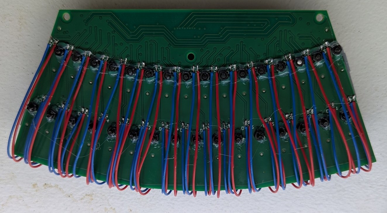
The wires for the 32 LDs are soldered to pads on the underside of the board. Then, hot glue is used to secure the M2 nuts, so it is possible to remove and replace LD holders from the top of the board after installation in the projector base.
A few more changes were made to the LD Holder 3D print design, to improve performance and reliability. After buying a micro-meter to measure thicknesses, I could verify a reference o-ring compression thickness to within 0.1 mm, and updated the dimensions of the flat surfaces near the o-ring (by about 0.1 mm) so that the laser diode would be level at a reasonable compression level (with enough springiness to push the LD upwards if needed during adjustment, but not so much that the o-ring was deformed and squeezed out through the gaps of the adjustment mechanism), established by feel when tightening the adjustment bolt with a small allen wrench. I was also concerned about the holders deforming over time due to uneven resin curing and shrinkage, so I thought I would lessen this possibility by using a transparent blue resin. However after attempting the print with this new resin, I found that the dimensions weren't quite the same as I had tuned for the previous resin, and the parts warped to a similar extent when left out in the sun for a few days. Thus I switched back to the gray resin, and included holes in the part to allow UV light to better reach internal sections. I tried scaling up to printing over 10 components in one run, which were mostly supports for the outside of the PCBs added as an experimental afterthought, and encountered the challenge of removing the printed pieces from the printer. Because they were so closely packed on the print surface, and so adhered to the metal, I ended up breaking many of the pieces during my attempt to remove them, which caused shattered pieces to fall into the resin underneath (which would then have to be filtered out to avoid breaking the printer on the next print), making the experience very frustrating. I was intending to print 32 pieces per run (it ended up being possible to fit 33 or more) and having to repeat that ordeal for over 8 times to get all the holders printed was out of the question. I did not want to change the holder geometry to improve print separation, because I had already optimized and validated many aspects of the design and did not want to start over again. After briefly considering giving up and sending the design to pcbway for fabrication, I made a substantial improvement in the printed part removal process. The printer came with a metal "putty knife" that I had been using to remove the parts, thinking this must be the optimal choice, which had a thick metal edge that would push the parts instead of separating them from the printing surface, requiring lots of force and often breaking parts. In place of this, I used a thin razor blade scraper (of which I bought a 10-pack on Amazon, and which came in handy for many other tasks), which would easily slide between the printed part and the metal surface, and the part would fall off with almost no force required. I also added diagonal tapers (instead of sharp corners) on the side of the holder contacting the metal, which would give a starting point from which the separation line can propagate. With this approach, printing large batches did not seem so daunting, and I started working towards the required 256 parts.
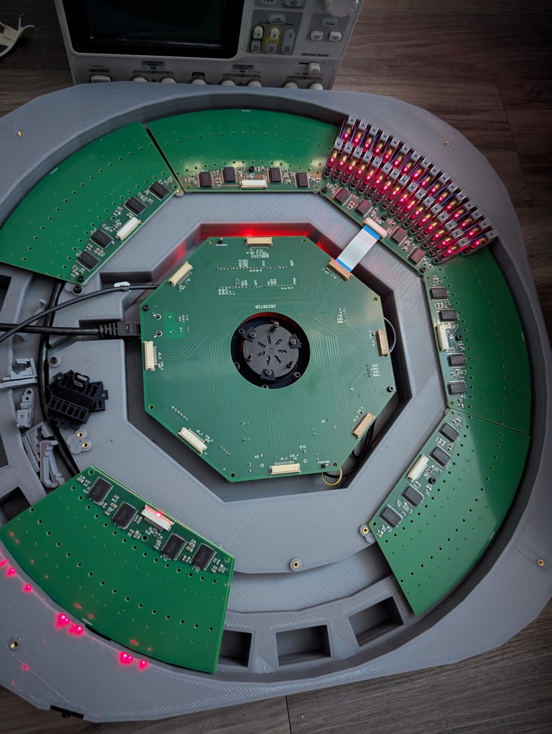
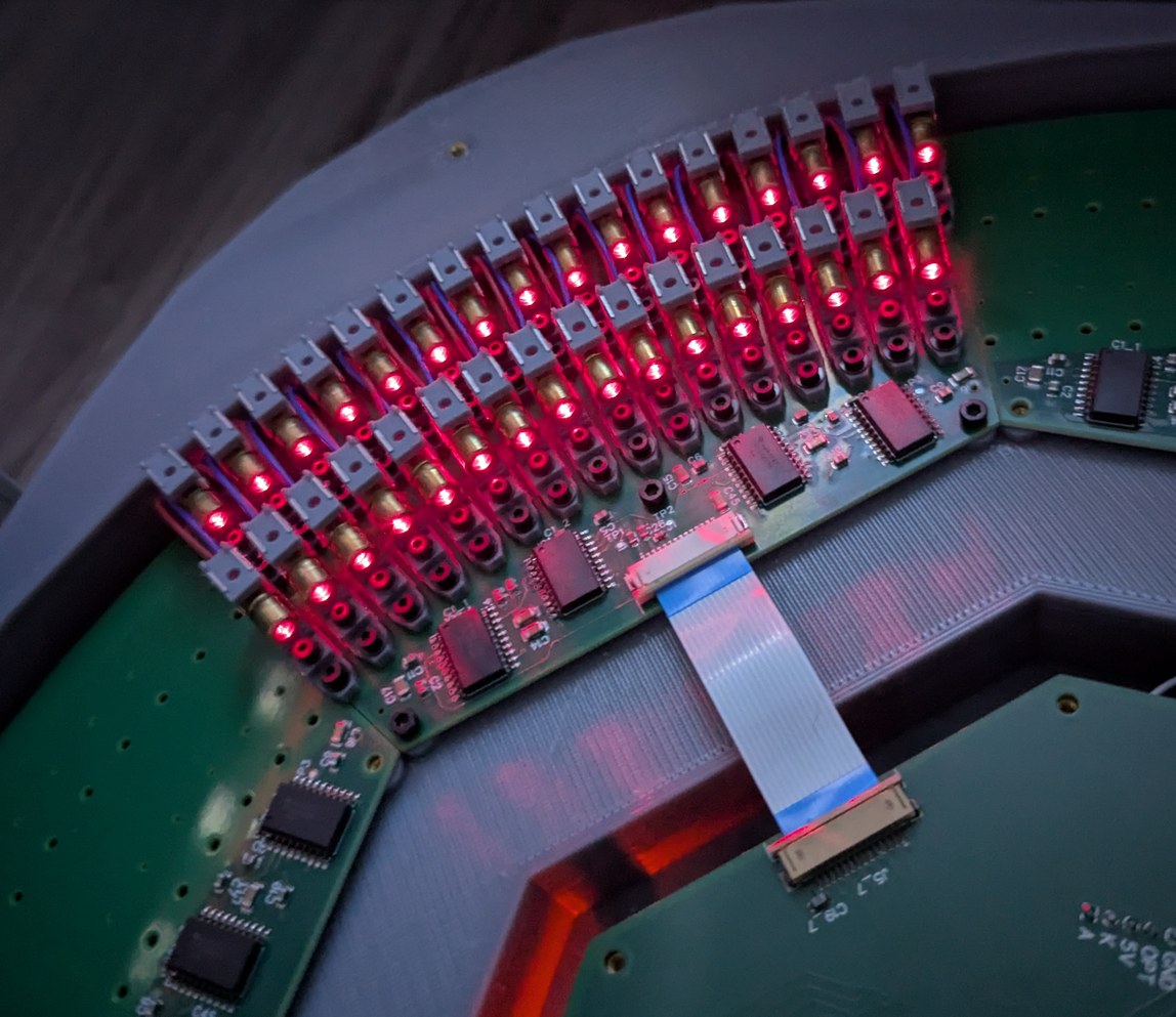
Installing the first 32 LDs in the projector to test their performance and difficulty of alignment.
Slow motion capture of scanning through 32 laser diodes, to test the first installed LD board. A single LD flashes every ms, which is too fast for the camera so multiple LDs appear to be on simultaneously in the frames. By eye, the entire board appears illuminated simultaneously, it is possible to tell there is some flashing but not possible to distinguish whether the LDs are illuminated from left to right or from right to left. In actual operation this rate will be over 10 times faster.
The process took multiple steps, all separated by multiple days, with batches overlapping when feasible. First I printed 33 holders at a time, followed by a rinse in isopropanol solution, and curing with UV lamps for about 10 minutes. Second the holders were left to sit on a somewhat sunny windowsill for a few days, to complete any curing or warping that may have been still going on and to allow volatile components of the resin to evaporate (this may have been more of an issue because the resin was multiple years old and stored without temperature control). Because the thickness of the holder exceeds 3 mm in places, this was a slow process; I could check the progress based on the feel of the printed part, even after initial UV curing it felt soft and rubbery, while after a few days on the windowsill the tactile aspect changed to more of a hard plastic surface. In the meantime I was preparing the laser diodes. I checked the wires that were soldered on, and for about half of the LDs adjusted the soldering so that the supply wire would be centered relative to the LD body, because it has to pass through the hole in the back of the LD holder. Then I checked each one for functionality and adequate brightness, and adjusted the collimating lens to have the beam focus at infinity (or, practically, reflected from a mirror across the room). The focal distance adjustment was quite sensitive, with even a tenth of a turn of the threaded cylindrical portion causing a visible widening of the laser spot. Then I used a low-viscosity "penetrating" threadlock fluid to lock the focus position, so that it does not change during further handling of the LD when installing it in the holder. Unfortunately, after the threadlock dried, some of the LDs ended up not focused as well as they had been during the adjustment, perhaps due to elastic deformation of some components before or after the focus adjustment step, so the focus was visibly imperfect, but with 256 LDs to get through I accepted that this error would be adequate and kept the process going.
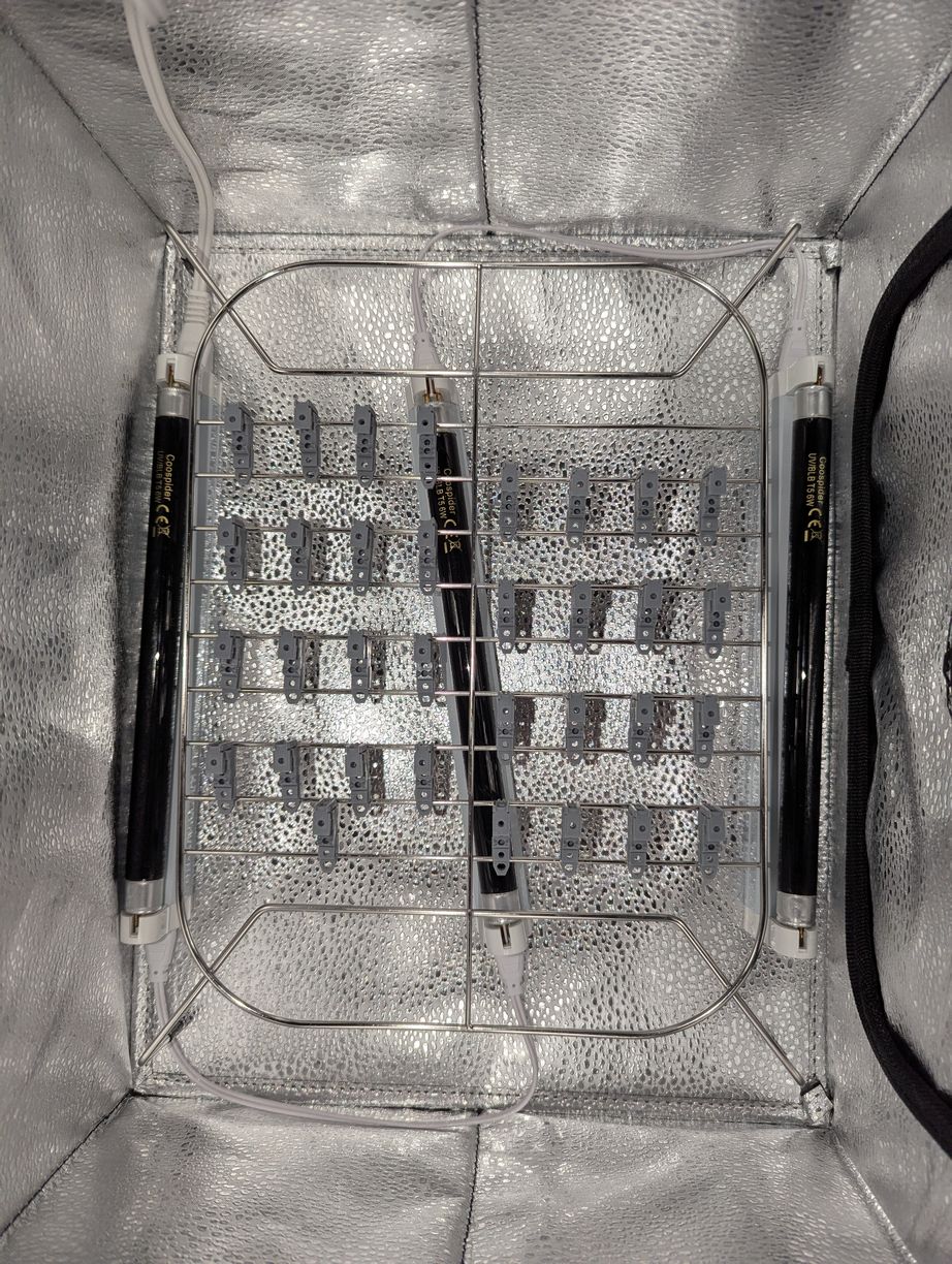
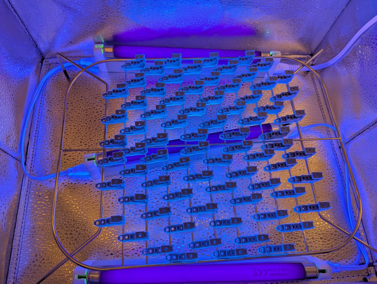
Curing a batch of LD holders in a reflective enclosure with UV lamps.
Third the holders were assembled with o-rings, nuts, bolts, and washers for the adjustment mechanism. Fourth, laser diodes were installed in the holders and then adjusted to be outputting a horizontal beam. Fifth, staples were added to improve preload on the LDs in the holders. Sixth, dowel pins were inserted in the holders and the assembly was attached to the PCB with bolts, washers, and nuts. Seventh, the LD wires were soldered on to their corresponding pads on the bottom of the PCB. Eighth, all 32 LDs on each board were tested for functionality when connected to the projector main board. Ninth the LDs were individually adjusted to point to the virtual center of the spinning mirror, in theta and phi directions. Tenth, the LD positions were locked with some combination of threadlock and hot glue.
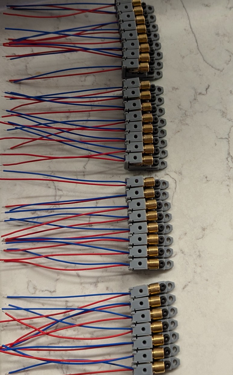
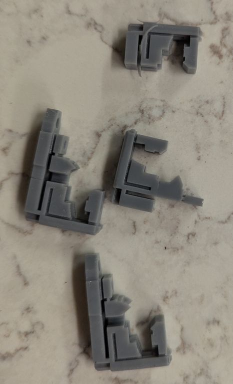
Left, a batch of 32 LD holders during assembly (this was repeated 8 times). Right, some LD holders that did not print correctly were found and discarded.
During assembly I realized a few design choices that could have been made differently to improve the project. First, the LD circuit boards could have been made larger, with holes for wires to pass through, instead of wires passing around the back of the board, as then there would be a surface at the back of the PCB to grab on to. This would help both with handling during assembly, and with alignment of the boards inside the projector base. With the present design, wires and the backs of LD holders were overhanging the back of the PCB, preventing any convenient way to grab that side of the board. I made that decision so that the projector would be a few cm smaller in size, however it would have been better to make the projector slightly larger while enabling the more solid mounting points if the PCB had continued back beyond the LD holders (the PCB could be secured in back and front, whereas now it is secured only in front and the back can flex relative to the front due to LD weight and inherent non-planarity of the PCB, changing the projected LD angles in phi). One aspect that surprised me was the weight of the assembled boards - an empty board was about 40 g, and with the LDs attached it was over 200 g. (Actually I had been worried that the projector would be too light and therefore prone to vibration from the motor, so the base contains pockets for adding ballast weights.) This mass was not enough to significantly bend the cantilevered PCB, however some of the PCBs were not fully planar to begin with, and for those it would help to have additional mounting points in the back. The boards could have also been made in a shape that matches the LD holders on the boundaries between boards, rather than being cut along a straight radial line which means the holders on both edges end up partially off the board (on the other hand, this helps maintain vertical alignment between adjacent boards as those holders form an interlocking structure). Second, the lid should have been designed to be replaced without a probability of bumping into the LDs. As originally designed, the lid simply sits on top and can slide around, while the LD holders extend about 6 mm above the bottom of the lid in order to allow for the widest projection angle. Thus when removing or installing the lid, there is a possibility for the lid to slide into the LDs and disturb their alignment. As a quick fix I heated up some metal rods and inserted them into the base, melting a hole in both lid and base, so the lid would have to be aligned with the rods before sliding down to where it could bump into the LDs, and at that point it would be prevented from doing so by contact with the rod. However this means that the rods are in the way of low angle projected beams, so I made the rods removable (later I calculated that by extending only barely above the top of the LD holders the rods can stay in place without interference). It would have been better to design the lid to hold the rods, and the base with corresponding holes, and there is adequate room within the existing design for this with minimal changes. Third the LD lateral adjustment was difficult because the bolt would act like a clamp (tilting laterally and pushing the LD holder into the PCB) when trying to move the LD holder. I'm not really sure how this could be done better given the space constraints, but maybe some mechanism with an off-center drilled cylinder could work. Fourth the LD holder coarse vertical steps were too large, and in many cases the LD would be at an awkward "intermediate" position where at one coarse step the o-ring would be too compressed while at the next coarse step the o-ring would be too loose. I kept track of which of the 5 coarse phi adjustment steps had been used, and it was pleasing to see that the middle position had the highest occurrence, suggesting that the dimensions I used for o-ring preload and step height were properly matched to the LD mechanical package. There was good utilization of the +1 and -1 positions, but there was only 1 LD of 128 which used the -2 position and none in +2. Thus the coarse steps should have been smaller, and then the 1 LD that would be an outlier could be replaced by another LD, instead of taking up 2/5 of the design adjustment range to include this 1/128 LD (by the end there were 1 or 2 LDs in both of the outermost positions). On the other hand, this additional coarse range proved useful in later pixel scale alignment, as it allowed for moving an LD to one of the outermost positions when it would have been impractical to take apart the board and replace an LD.
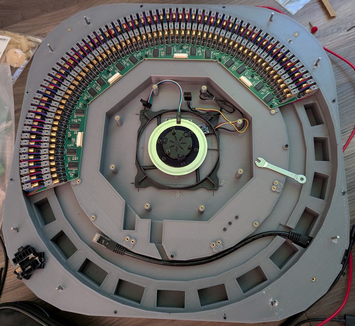
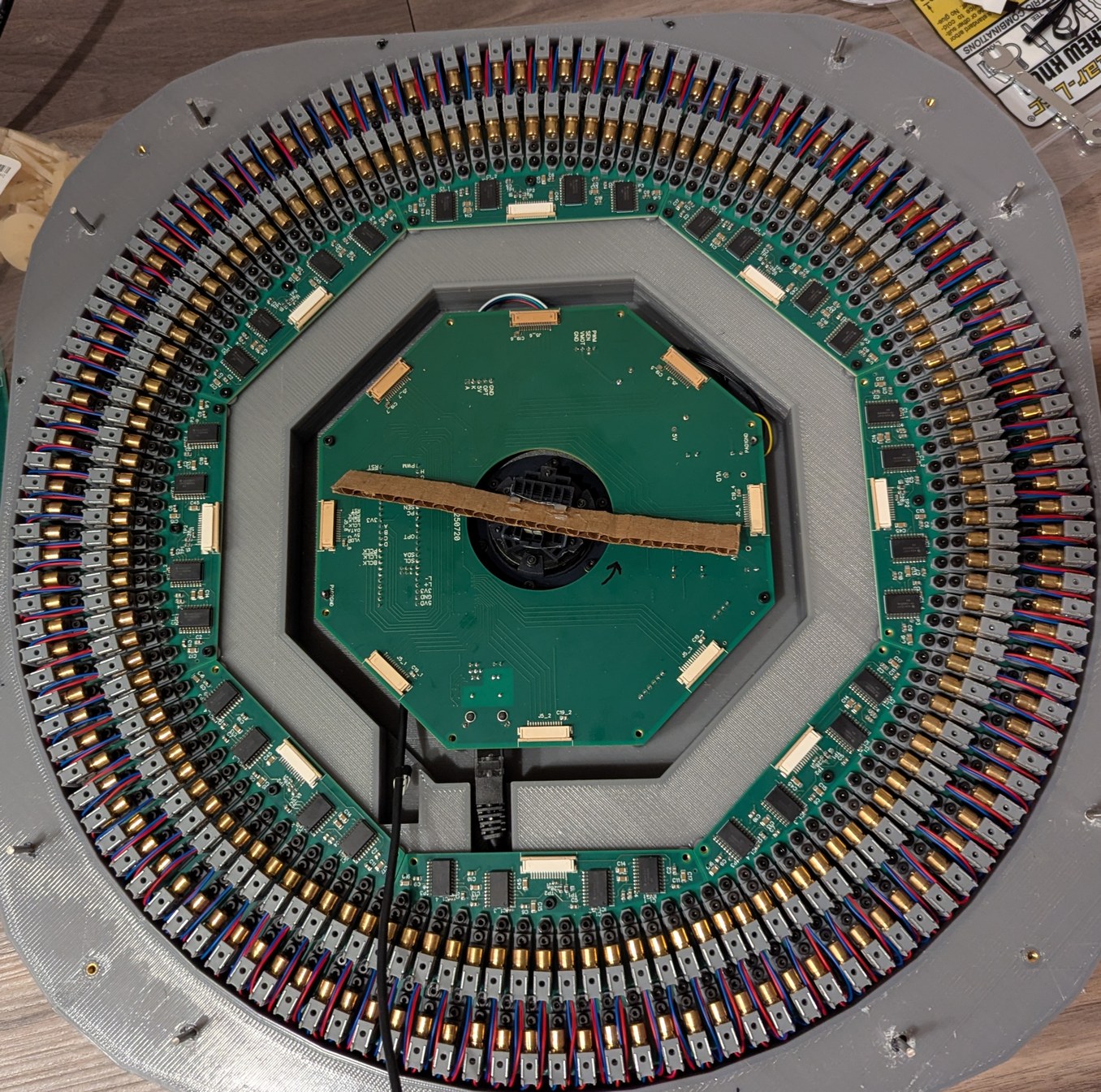
Assembling the LDs and boards. Left, 128 LDs done, with the new encoder ring and motor and accelerometer visible. Right, all 256 LDs done, with the main PCB connected and a cardboard model of the mirror installed on the motor.
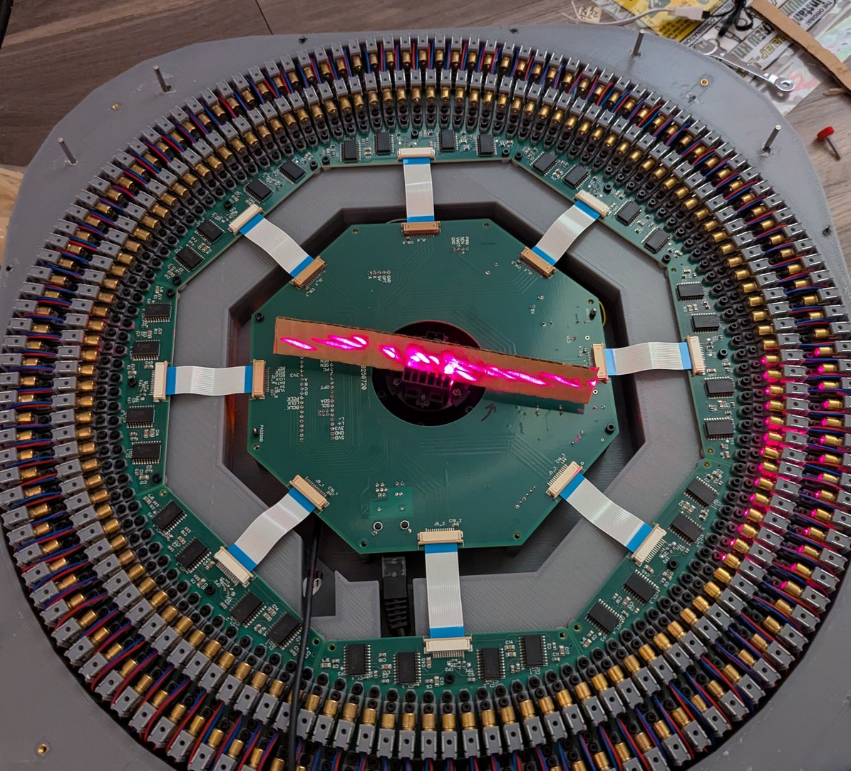
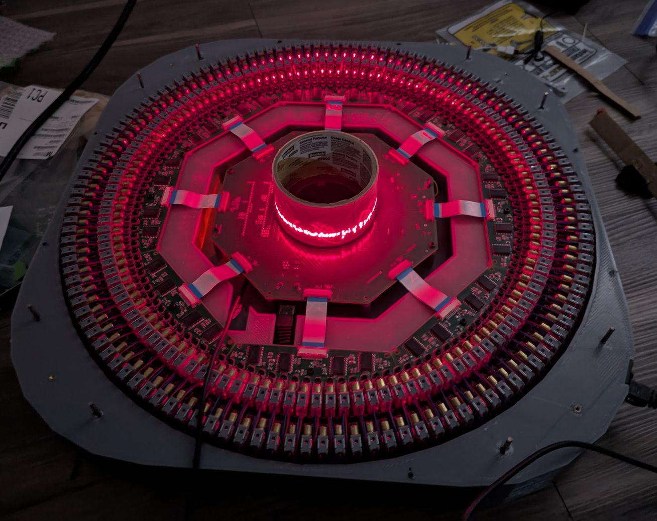
Turning on a laser test pattern with all 256 LDs, with a cardboard mirror model, and with a roll of tape in the center, to better visualize the laser beams.
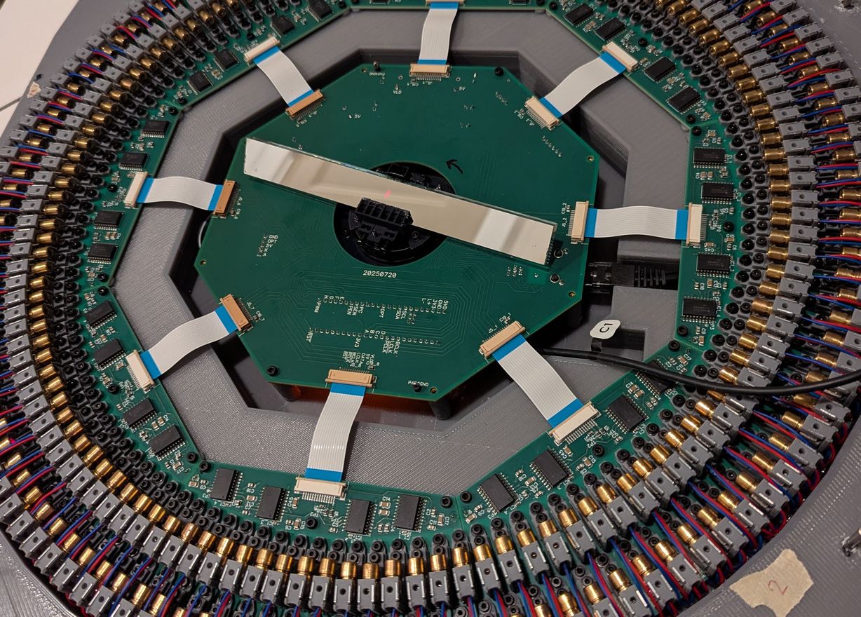
I couldn't resist putting the real mirror in the holder, to get a preview of what the projector will look like after LD alignment is completed.
I was saving putting in the mirror for the last step, as that would minimize the chances of getting fingerprints on it while working on other parts of the projector. However I needed to get a sense for the motor voltage and current that would be required, to avoid changing motor voltage when the mirror is installed (unfortunately I did not include a voltage measurement divider on the motor voltage line, and the motor always spins when powered up, which makes it difficult to access top pins for measuring the voltage manually as the mirror would be passing directly over them). I was getting worried that the boost module for the motor was unnecessary, because with no load on the rotor (other than the mirror holder) it would spin up to 3600 RPM at only 7 V input. For safety reasons I would not want a mirror spinning this fast, but I wasn't sure how much of an impact there would be from aerodynamic factors once the mirror is installed. I made a quick prototype out of cardboard that matches the size of the mirror, glued it in the holder, and tested the speed. Despite the mirror (or cardboard) not being propeller-like, in particular having the angle of attack on one side be the opposite of that on the other side so no axial force would be expected, there was a significant impact of the mirror presence on the attainable speed. With the cardboard piece installed, the motor only reached 1170 RPM with a higher 12 V input, and drawing approximately 0.45 A at 12 V. It did not get to 1200 RPM until 14 V, which is over its 12 V rating. Substantial air movement could be felt all around the projector case, due to the cardboard piece acting as a radial blower. I guess this is why music boxes use air drag mechanisms like this to maintain a constant tempo - at some point the power required for a slight increase in RPM becomes very steep, so the speed is largely fixed despite variations in driving force. Compared to an unmodified fan, the current draw at 12 V was similar which was good for long term use, however this power requirement caught me a bit by surprise (and the rotor seemed to be getting quite hot, because the air flow wasn't as good as what the fan blades would provide at that speed); I had thought the aerodynamic effect would be minimal, but likely it will end up being the highest power draw of the whole projector. The significant air motion introduced vibrations much beyond the amplitude expected from a slight imbalance of the mirror, so I did not seek to do further measurements with the accelerometer, and instead hot glued the fan motor to the projector base (in addition to using the mounting bolts) for greater rigidity. Still I would be limited to not even 20 Hz update rate, opposed to the target 30 Hz which was chosen for low strobe effect, and minimum 18 Hz for the theta observer code (set by the slowest QTimer divider). I also had a smaller mirror, which I did not think I would use as it reduces the optical acceptance angle, however there may be an advantage to using it if it can spin faster. Making a second cardboard prototype, I found that the smaller size could spin to slightly over 1500 RPM at 12 V and similar power draw. The optical requirement of a long mirror is not favorable here: the velocity of the outer tip of the mirror is high, which causes air drag and potential for damage from hitting dust particles.
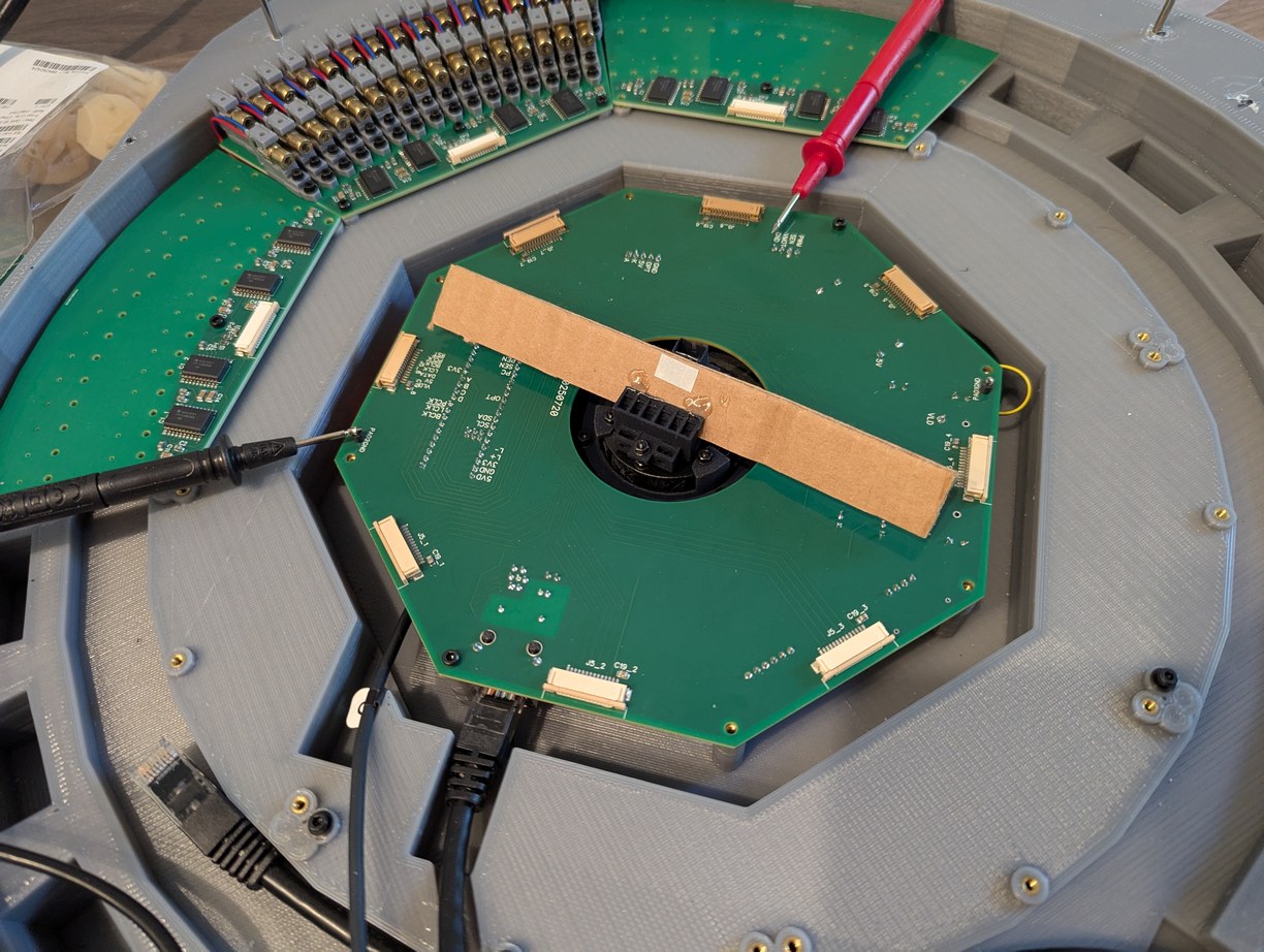
Adjusting motor voltage with the cardboard prototype. The motor always spins when powered on, so I had to measure the voltage on the pins under the cardboard by carefully sliding the voltmeter probe from the side. Then I used a small screwdriver to adjust a potentiometer on the boost module under the main PCB. This could have been better designed.
Slow motion capture of scanning through all 256 laser diodes, before alignment and with a cardboard mirror model in center, to test the data communication. A single LD flashes every ms, which is too fast for the camera so multiple LDs appear to be on simultaneously in the frames.
Having assembled the LD holders and attached them to the LD PCBs, then soldering all of the leads with a soldering iron whose tip was almost flat due to erosion, I then installed the boards in the 3D printed base and began the process of LD alignment. By the end, I had used all the LD holders I had printed and even pulled in two earlier prototypes; I printed 297 copies of the final revision holder, of which 43 failed due to resin adhesion issues (pieces of the holder separating or not printed). I found that if I used 12 mm long bolts for the back LD holders, the bolts would reach the next lower surface of the base, and would thus provide vertical upward support to the back of the PCB which would otherwise be cantilevered. So even though this was not originally part of the design, I used the longer bolts on the corners of each PCB. Other bolt lengths ranged from 8 mm to 12 mm to use up more of the M2 bolt set that I bought, with preference for shorter bolt lengths in the sections under which the ethernet cable passes. The USB cable was still necessary to program firmware, and this cable had to pass over top of the PCBs where it risked hitting the LD holders and moving them out of alignment; it would have been better to include a feedthrough USB connector similar to the ethernet port so this issue could be avoided. I included shim washers under the 3 main mounting points of the PCBs (chosen for a somewhat kinematic mounting) to minimize bending of the boards after tightening the mounting bolts. Unfortunately I only remembered to use the shim washers after I had installed the boards, so I had to insert the washers from the side and push them under the board using a toothpick and some tape, making sure I did not drop any washers into the projector as they could later cause a short-circuit if they moved into contact with exposed terminals. The boards were divided such that on each edge there was an LD holder hanging off to the side, which helped with interlocking of adjacent boards into a similar plane; this meant that it would not be possible to take out a single board, at a minimum two boards need to be removed by lifting both at an angle so the interlocking holders can separate. Thus I sought to minimize the need to remove or adjust boards after they had been installed. Hot glue was used to secure M2 nuts on the underside of the PCBs for the LD holders, meaning that individual LD holders could be removed or adjusted without access to the underside of the PCB. Dowel pins were used to set theta spacing of both front and back row of LD holders, with the expectation from initial LD characterization that reaching the full theta adjustment range would mean that some of the back LD holders would need to have the dowel pin removed to get an extra degree of freedom for the laser beam to pass between the two LD holders in front of it. This also ended up being the case, for which I would remove the M2 bolt of the LD holder (using a small magnet on a hex key to reach in the tight space between LD holders without disturbing the alignment of neighboring ones) and remove the holder from the PCB, take out the dowel pin, and then re-install the LD holder and bolt. Dowel pins were also intended to be used for aligning the PCBs to the projector base, however the holes for the pins did not print accurately in the base part, so I aligned the PCBs by eye, with any non-idealities taken up by the LD holder alignment step. I still used the PCB dowel pin holes to maintain consistency after installing the PCBs, by melting the dowel pins into the plastic with a soldering iron.
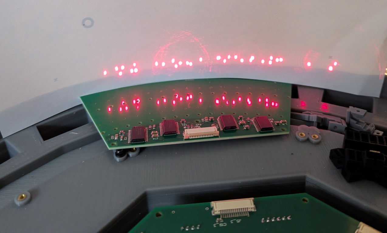
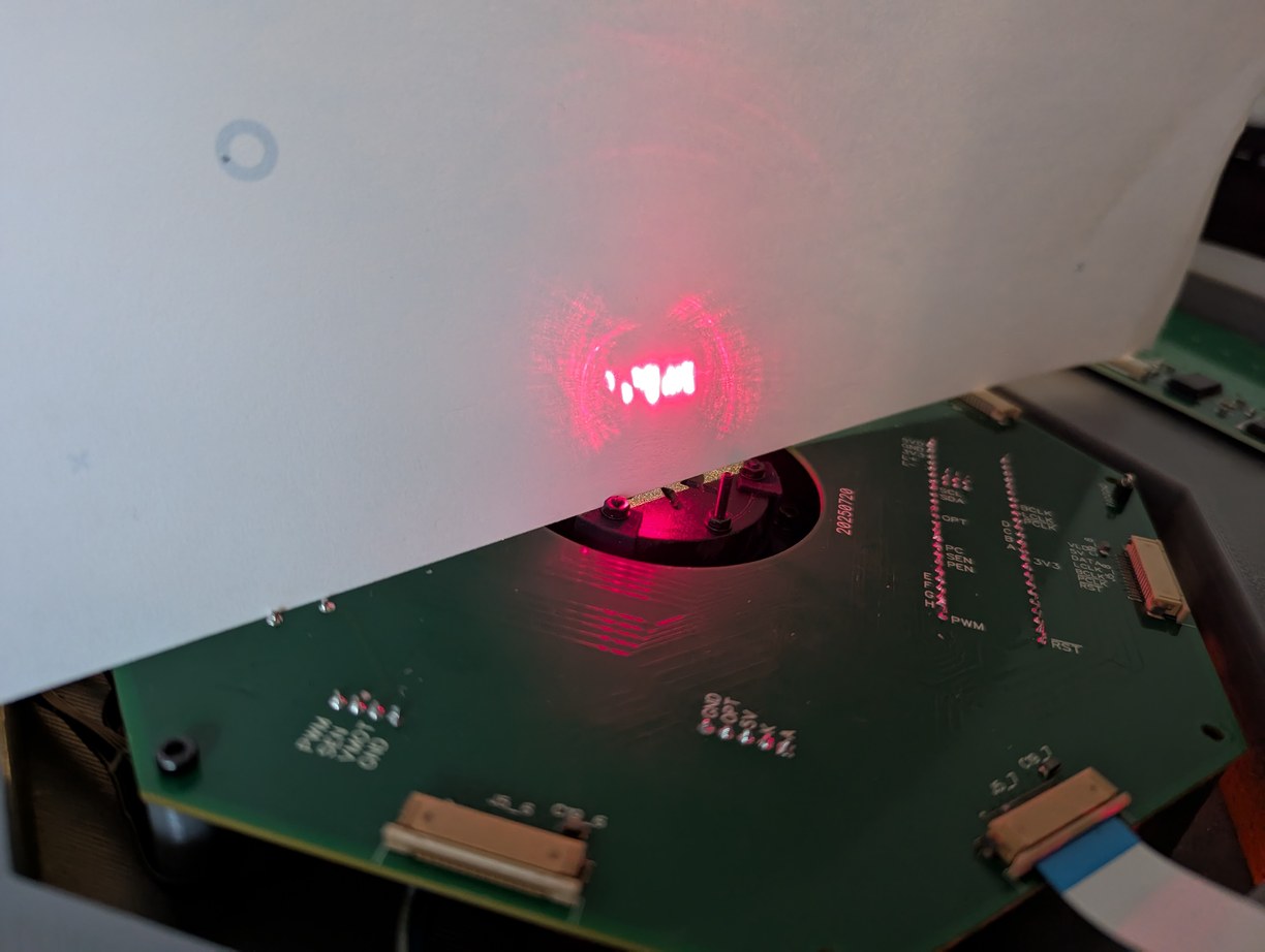
Dots formed by the first 32 LDs before alignment. Left, a piece of paper is held at the projector circumference, and right, passing through the virtual center point. In both cases the dots are irregularly spaced, despite initial fixturing by the LD holders and dowel pins.
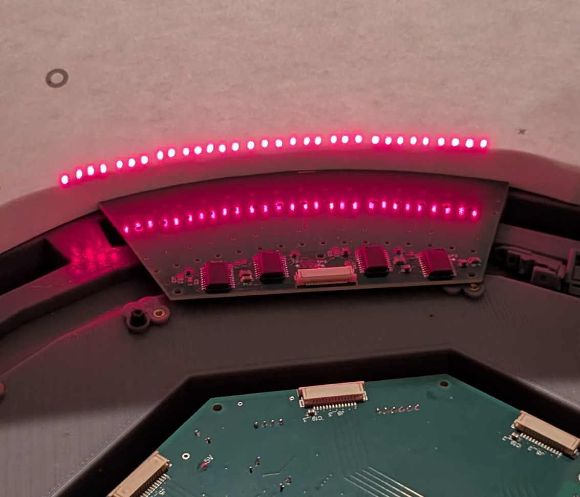
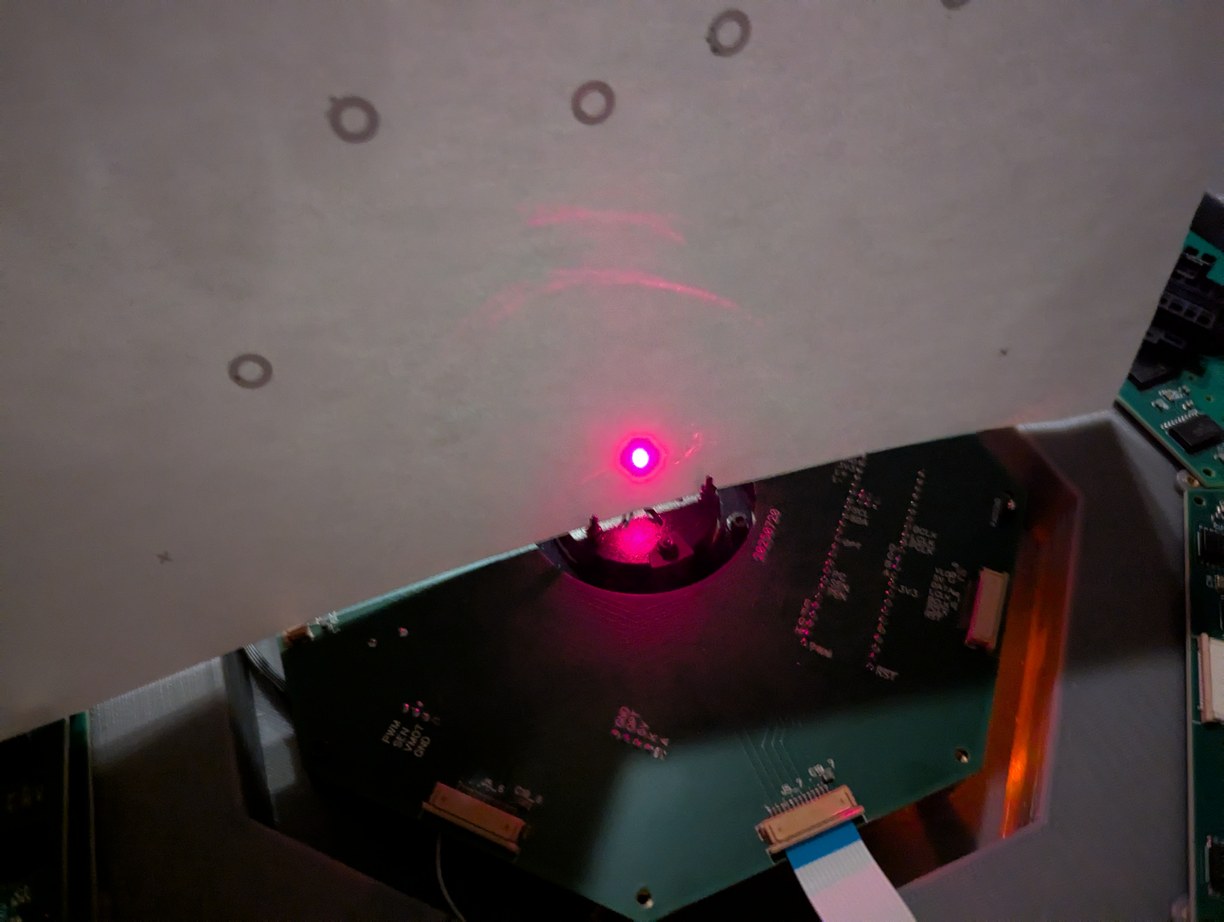
Dots formed by the same LDs after alignment to the centering structure on the back of the mirror holder. The dots at the circumference are regularly spaced, and all beams intersect at the virtual center point as intended.
For the first PCB (32 LDs) I aligned the LD holders by using the back section of the mirror holder installed on the motor. This was an aperture slightly separated from a flat surface, working on the pinhole camera principle, such that if the laser beam is aligned to the mirror center, it passes through the center of the aperture and lands on the center of the surface behind it. The LDs were pulsed at low duty cycle so the beam could be viewed comfortably. This approach worked reasonably well, however due to the motor cogging torque, this required using one hand to hold the mirror holder at the correct angle, while using the other hand to adjust the LD holder. I found that a more convenient method was to remove the mirror holder and to aim the laser from one LD into the LD directly opposite, which implies passing through the center of the assembly. This allows using both hands to adjust the LD holder, and the method works even when the LDs on the opposite side are not well aligned, because lateral displacement errors have a small effect on angular pointing direction due to the distance across the projector. As long as the LDs are known to be largely uniformly spaced around a circle, which is achieved with the LD holder dowel pins on circular arcs and visual alignment of the PCBs, aligning the LDs to each other will give a reasonably uniform pixel basis. I used a 6 mm wide piece of paper placed in front of an LD, then powered on the LD opposite the paper, and adjusted the holder of the latter LD so the laser beam would strike the paper in plane with all the other LDs. The LD holders somewhat adhered to the PCB and the bolts, which might be good as it would help maintain stability after alignment, however during alignment this required a few extra steps to first break the adhesion between the parts, after which the full adjustment range could be utilized. In a few cases I had to take out the LD holder and redo the coarse adjustment of the LD, which was possible to do without disturbing surrounding LD holders. Overall the process was slow - it took a bit over a week to complete (with lots of break time, so I could maintain focus on the process while active) - but hey, this is more lasers than the NIF. I was really hoping that this process would not need to be repeated due to parts becoming misaligned over time (due to plastic deformation, vibration, or some other factors). Nonetheless it was feasible, with the theta and phi adjustment mechanisms functioning as intended, so all LDs were able to be aligned. Having gone through this process, unfortunately I did not feel a sense of accomplishment, as I was ready to be finished with this work but there were still more alignment steps to do. I put in a small mirror to test the projected beams, and saw a uniform line of points as expected.
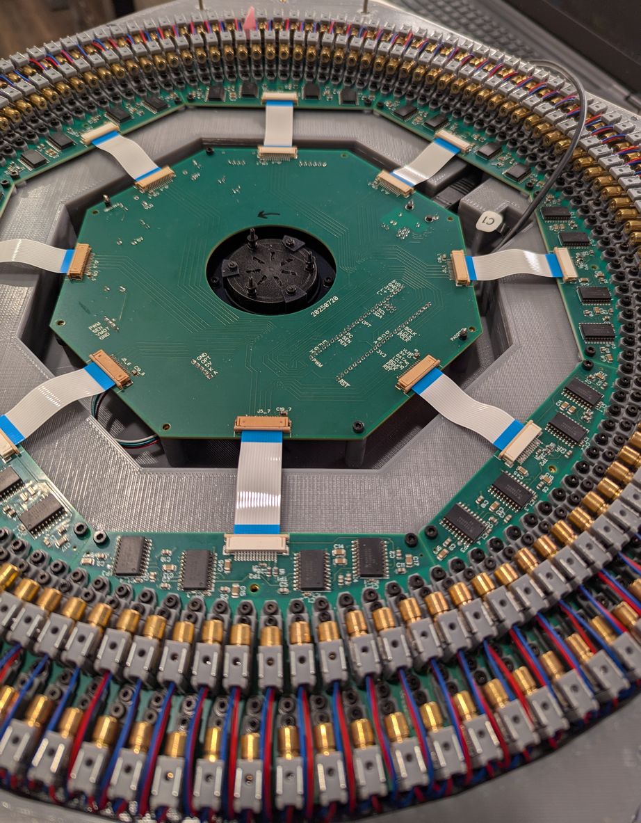
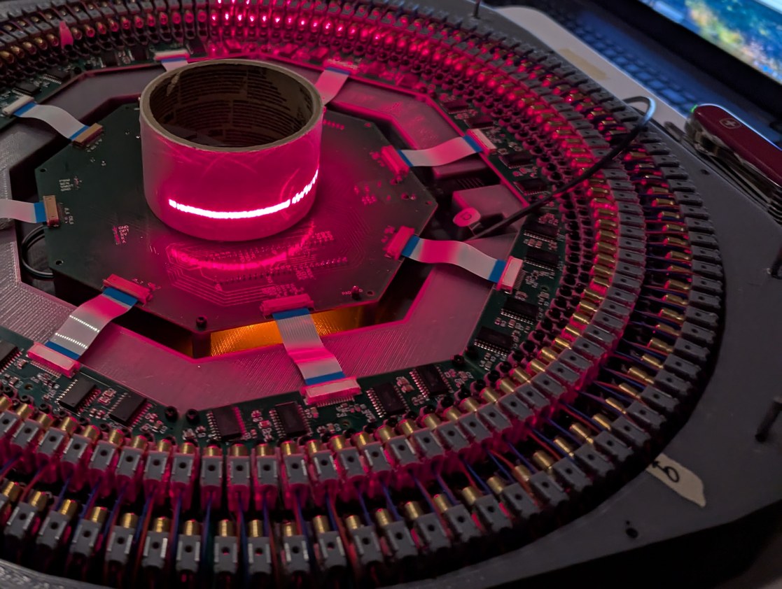
Rather than aligning to a centering structure, the remaining LDs are aligned by aiming them at the LD directly opposite; in the first photo a piece of light red paper is used to demarcate the opposing LD for this process. In the second photo, with a roll of tape for visualizing the laser beam path, the lasers towards the left have been aligned while those towards the right have not been aligned.
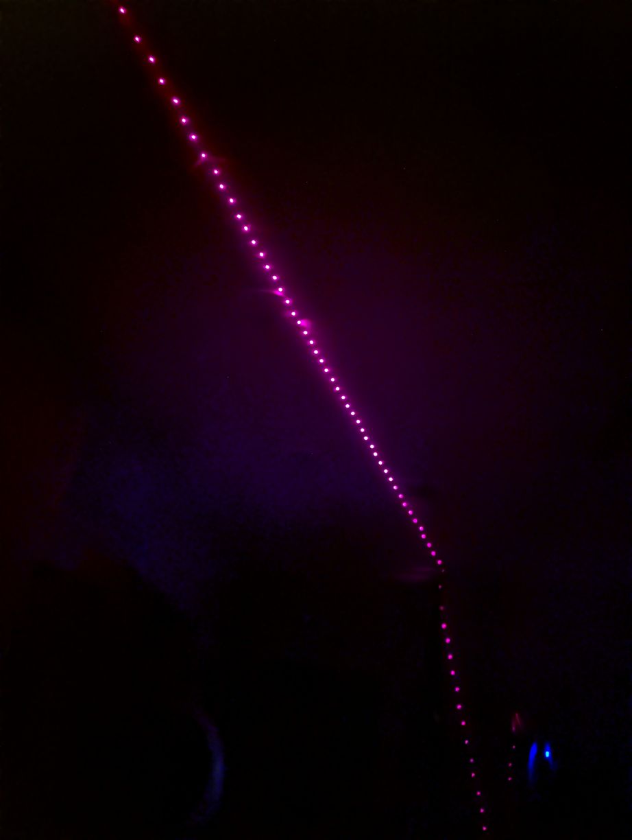
Placing a mirror at the virtual center point, the reflected beams form a nice line on the ceiling.
Next it was time to insert the large mirror. As I already had the mirror holder designed for the large mirror, I used it instead of the smaller mirror, despite the aerodynamic speed limitations discussed above. I found the balance point of the mirror using a thin wire on a flat countertop (this could have been done as well with just a ruler to find the half-way point along the mirror length, since the mirror is of a uniform cross section), and marked it for aligning with the mirror holder centerline. Then I glued it in the holder using a thin layer of expanding "Gorilla glue" (the holder was designed with small indentations into which the glue can expand to help lock the mirror in place, as in earlier testing I found that the glue adhesion to glass was actually better than adhesion to the 3D print; still I underestimated the amount of expansion so the holder was slightly strained by the mirror + glue thickness exceeding the originally intended size), and balanced the holder again using the wire and adjusting M2.5 balance bolts to bring the center of mass towards the geometric center of the holder, which would in turn coincide with the axis of rotation above the fan motor. Initial tests of the large mirror with the aligned LD holders confirmed that my calculation of angles was correct and that the mirror width and height were adequate for the lowest projected angle of about 87.7 degrees from vertical (set by the top surface of the inner row of LD holders).
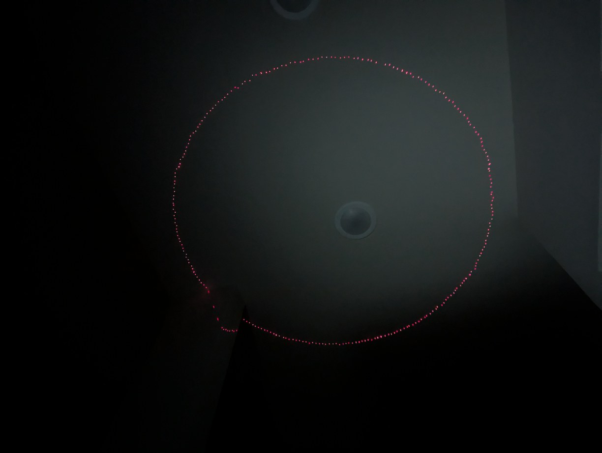
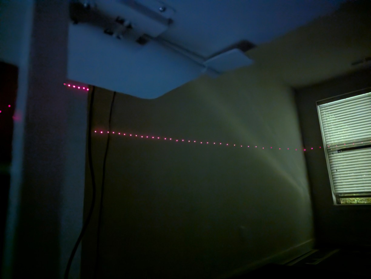
With the large mirror, I could plot a circle near zenith and near the horizon, for confirmation of angle range and theta tracking.
After spinning up, I encountered some trouble with theta tracking: even at maximum power the rotation of about 18 RPS was too slow with the large mirror, and the fan motor was heating up above 40 degC (on the outside). I implemented a clock divider for the pixel clock to enable lower speeds down to 11 RPS, as at low power the motor would spin at about 12 RPS with only 0.3 A current draw (before the voltage booster). This lower refresh rate was not as unpleasant to look at as the one-dot flicker tests suggested, which was a relief. Then the tracker did not keep up with changes in theta-pixel shift; after lots of debugging I realized this is due to the multiple buffers of COMP1-CMPLD1-buffer, which meant that I need to implement a minimum time cutoff (otherwise it will simply skip one or more pixels and result in a loss of lock to index position). With that fixed, I was able to get patterns projected. While the fan motor without any load was seen to be very stable in speed, with the mirror there were varying aerodynamic loads and the speed was not as stable. I changed the gains of the theta tracker IIR filter to use less averaging for omega, which made the projected image more stable, though still if looking at the projected dots very closely they can be seen to slightly wander in their position in each mirror pass. In principle the 256 encoder rising edges could be all used to lock the projection more rigidly with the rotor (instead of using one in every 16 as at present) but this did not seem worth the effort as the fluctuations were not significant (maybe 1/20 of a pixel spacing).
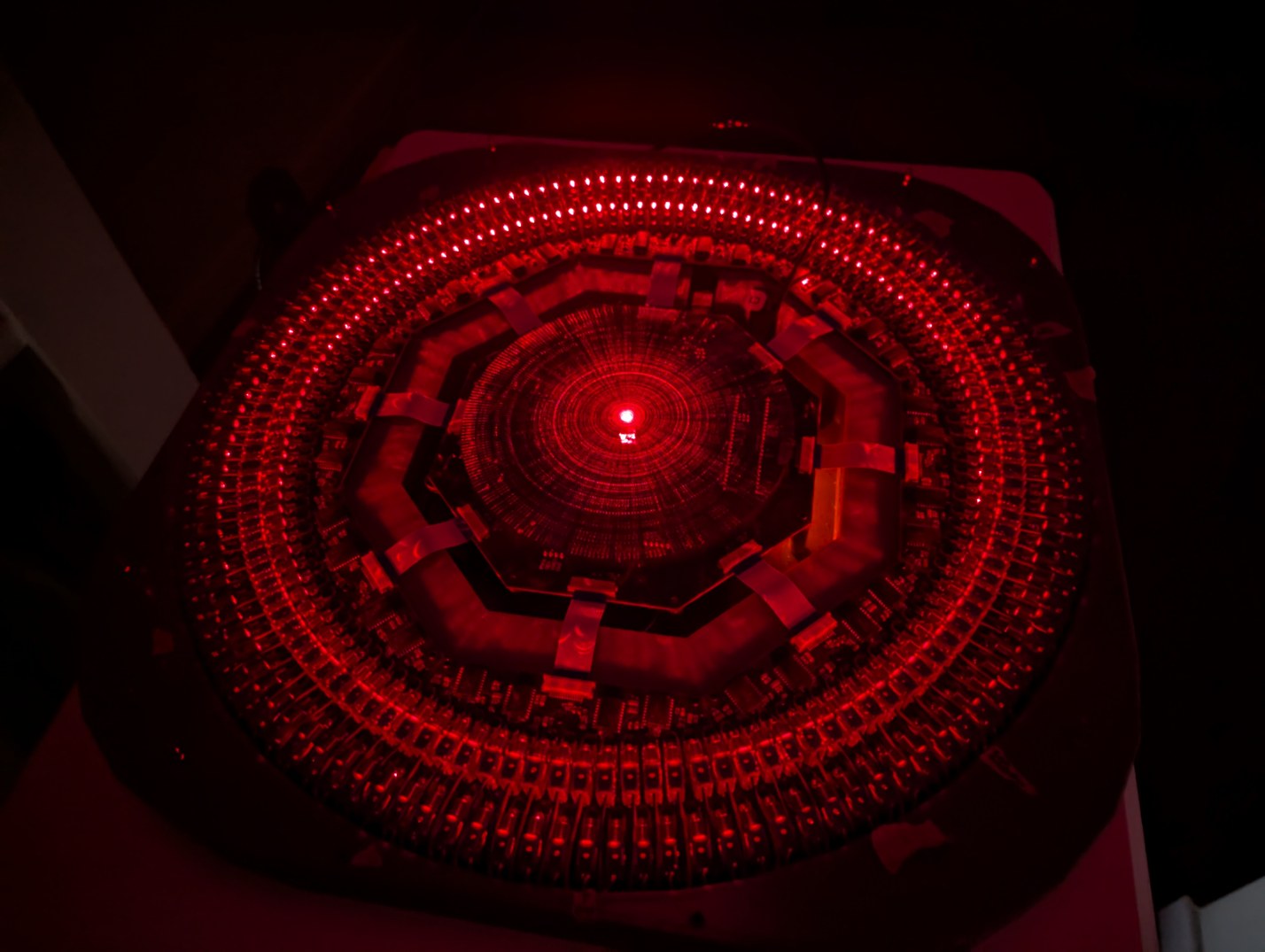
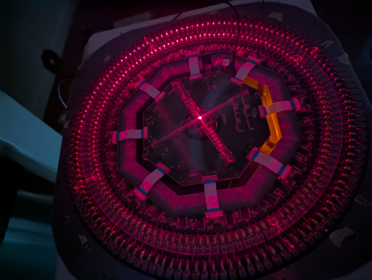
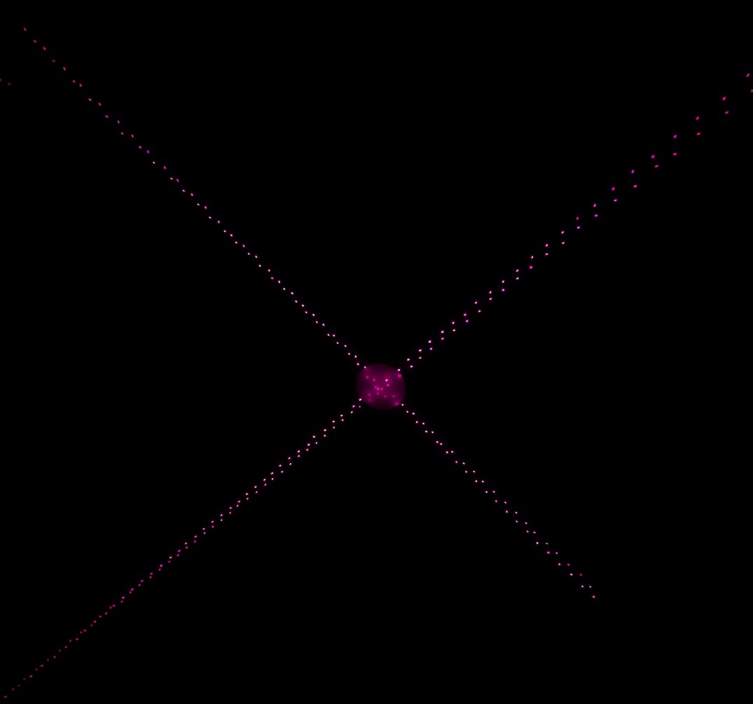
Appearance of the projector when rendering a full-pixel scene, and when rendering two intersecting lines. Rightmost, a photo of the intersecting lines pattern projection, with lines being split into two parts due to pixel misalignment.
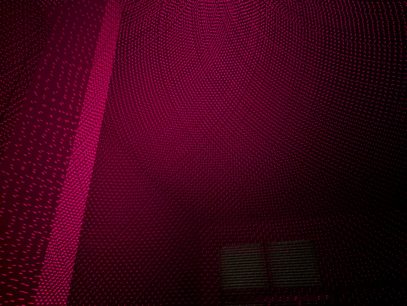
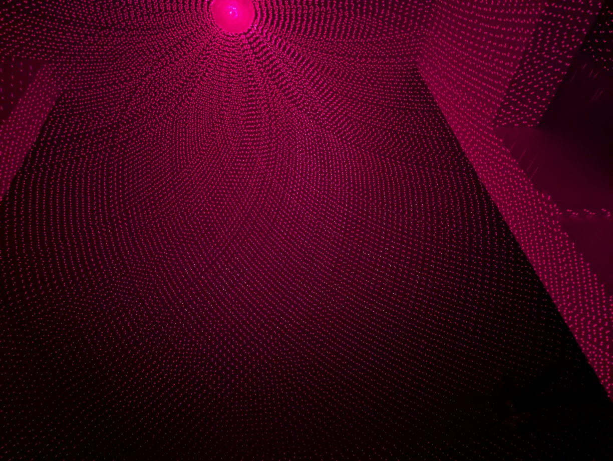
Two views of the full pixel grid, towards the horizon and towards zenith. The alignment at the pixel level is not very good.
However the pixels were not displayed in a nice grid as intended. Partially this is due to the mirror tilt angle not being precisely 45 degrees, and partially due to the LD holders not being aligned to the axis of rotation but rather to opposite LDs from the previous alignment step. Also, with the pixel strategy used here, each LD draws a segment on both the "rising" and "falling" edges of the mirror rotation, which makes a strict requirement on the mirror, LD, and rotation axis angles to match the ideal values. If only one of the two edges were used, the pixel resolution would drop by a factor of 4, but alignment would be much easier. How can I achieve the proper alignment? It is a bit of a "chicken and egg" problem, because I don't know what the axis of rotation is, and if I pick some point and align all the LDs to it, I might be "aligning to a cone" if the mirror is not at 45 degrees to the axis of rotation. If this happens, the laser arcs will not be at correct angles for the pixel scheme to work, so they might make a grid in some regions of the projection while other regions look irregular. I started by aligning patterns with 5 laser beam crossings, using 4 lasers 90 degrees apart. It is possible to get all the lasers to cross when they are at 90 degrees to the axis of rotation, without necessarily assuming an ideal mirror angle (although theta and phi can offset each other, so it is possible to introduce a net shift in one or the other if not starting from a centered orientation). This concept is illustrated by the 5 intersection points in the first figure of this article. After the intersection alignment, I used a circle pattern and adjusted the LDs by eye to make a uniform circle. Without an absolute reference, such a "crowd consensus" approach is no guarantee of proper alignment (as the theta and phi adjustments could have a common mode error), but I hoped that it would mostly help the situation, which seemed to be the case. At this point I began to see some signs of a square pixel grid, but it would only cover a small area, becoming irregular at other points due to angular mismatch. I needed to determine whether this was due to the mirror angle not being 45 degrees or due to lasers not being fully aligned, so I would not be chasing my tail with aligning and re-aligning a system that cannot form a complete square grid.
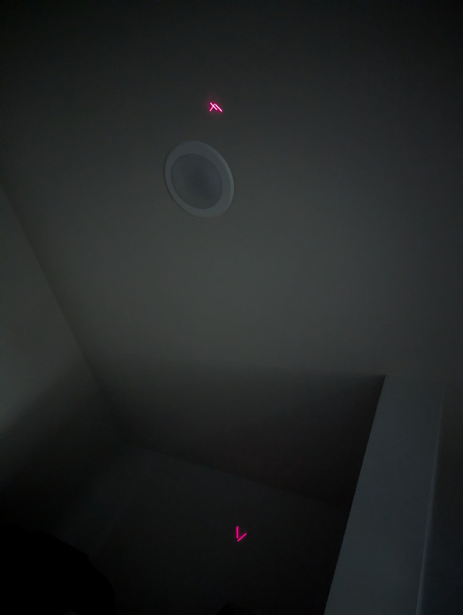
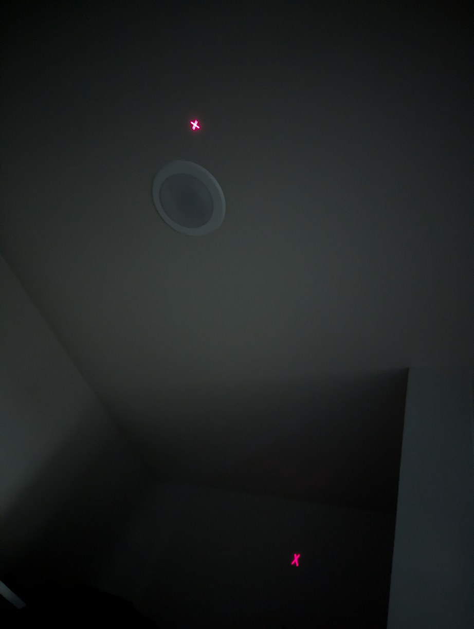
Aligning pixels by crossing Xs, on left before and on right after alignment, with 3 more Xs around the zenith which are out of the field of view of the camera which all need to intersect.
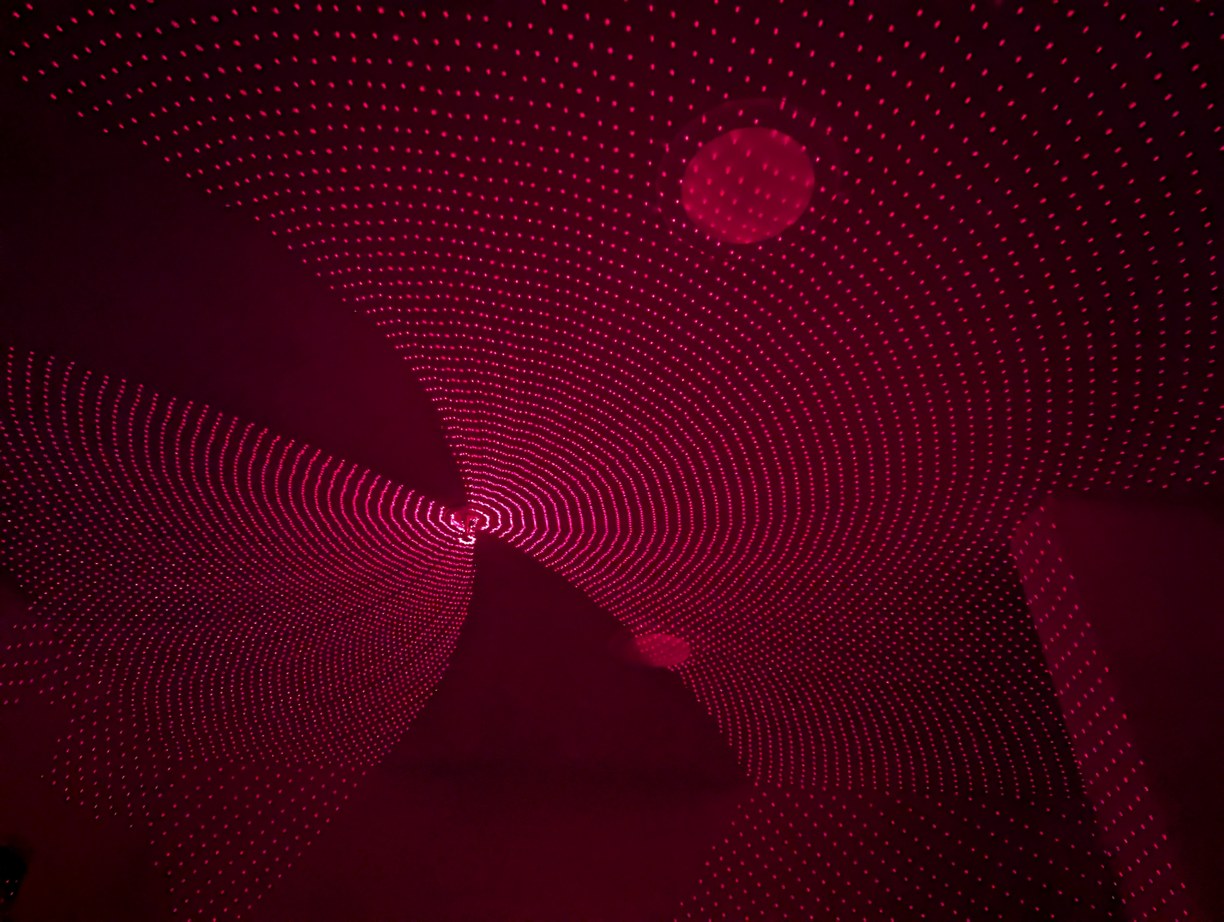
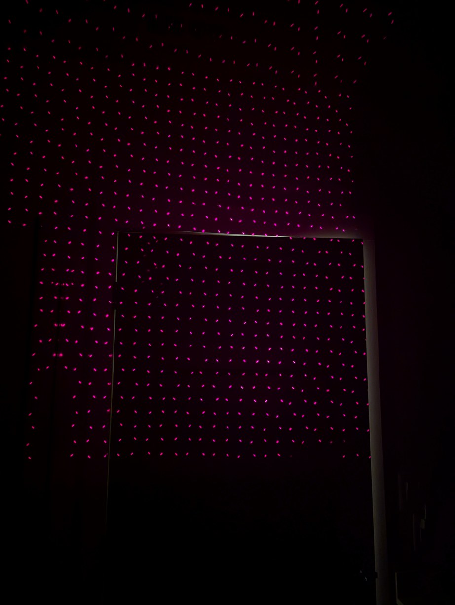
After X alignment, the latitude lines looked more clearly circular, and small portions of the field near the horizon started to appear as a square grid. However there was still something in error (maybe mirror, maybe LDs).
For this, I came up with the idea of using a 90 degree reference tool. This would be made by attaching two laser diodes to a piece of aluminum extrusion and aligning their beams to be intersecting and perpendicular. If this is held over the spinning mirror, the mirror will reflect both laser beams toward the source diodes only if the mirror itself is at 45 degrees to the axis of rotation. (There is also the need to ensure the plane of the perpendicular beams contains the axis of rotation, which is done by marking the line that the reflected laser spot sweeps on the part, found by aligning another piece of extrusion parallel to one beam and tilted to reflect the other, then the reference is adjusted until the reflected line is parallel to this marked line.) I verified the 90 degree angle of the perpendicular beams by measuring a triangle formed by the projected dots and the intersection point, and also by dividing a full circle, with expected accuracy below 0.1 deg (nominal pixel spacing is 0.7 deg). At the 0.1 deg scale, the mirror angle changes over minutes due to heating up of the fan motor, so there is not much advantage in trying to achieve higher accuracy.
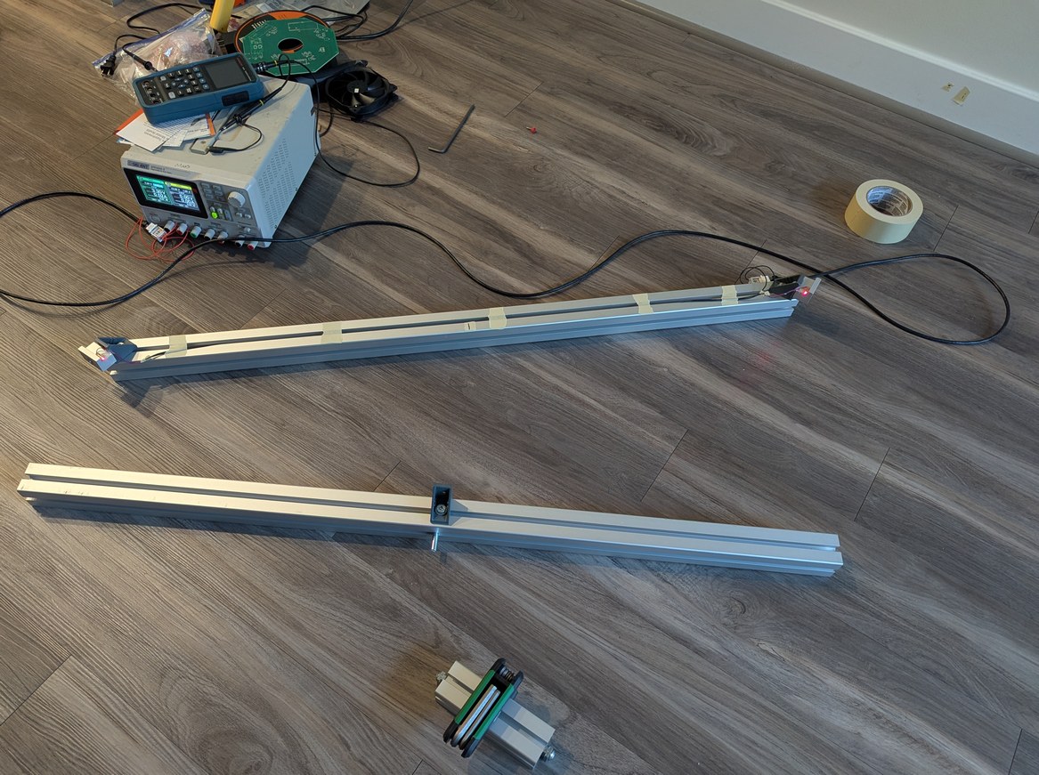
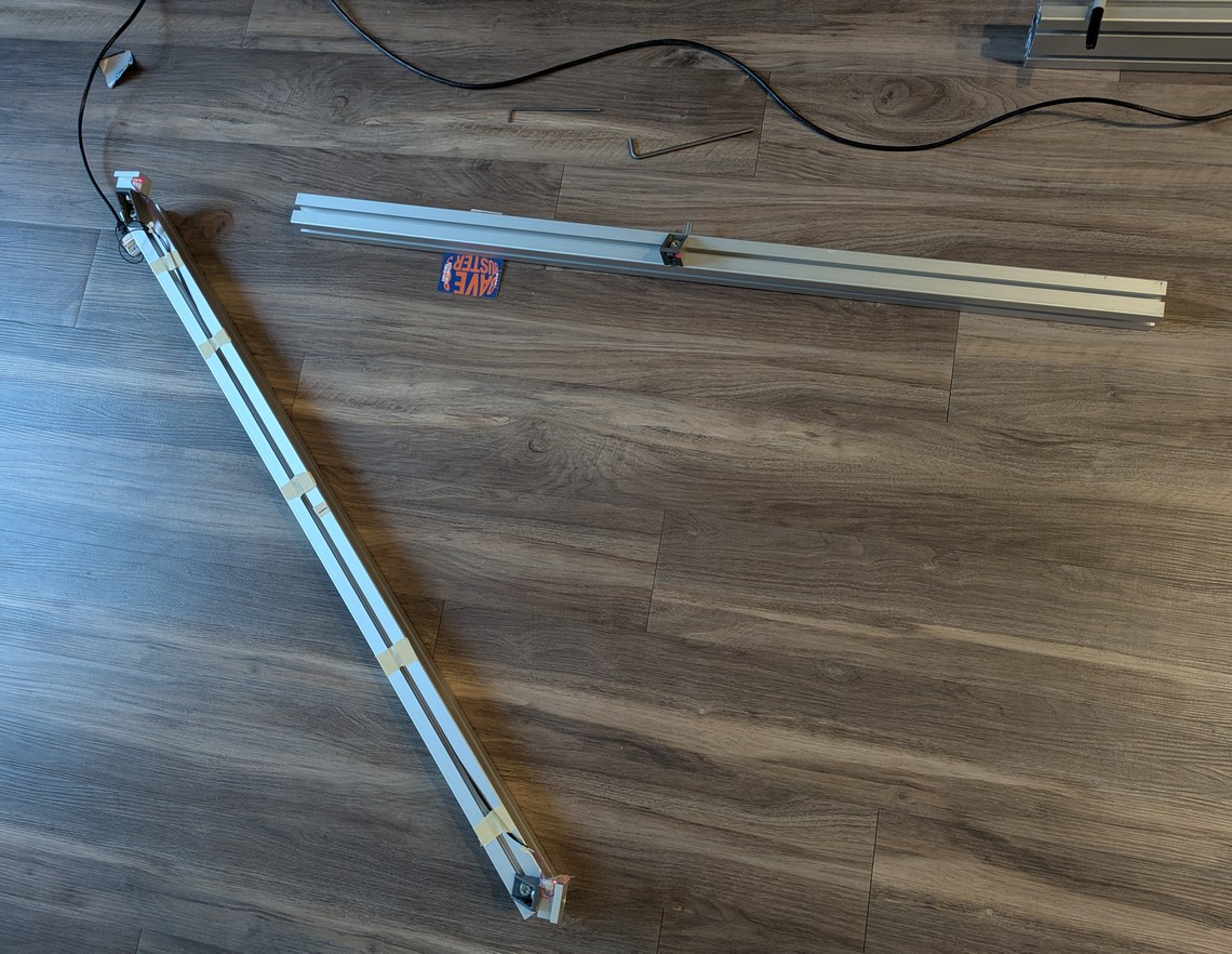
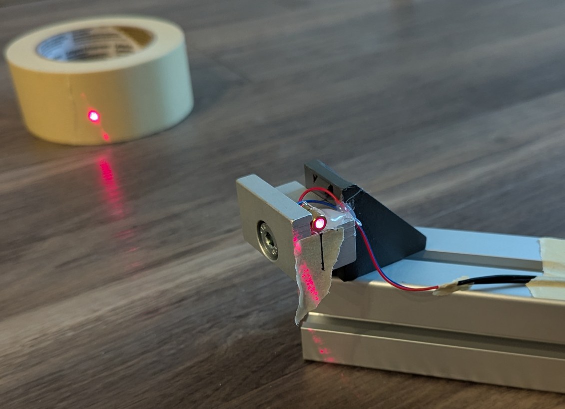
Preparation of the 90 degree reference, by attaching two LDs and ensuring the beams intersect at 90 degrees, through measuring the projected points on a distant wall. Further, a mirror is aligned to the beams (using a card to align the entire length of the aluminum extrusion) and used to draw a line under the LDs onto which the laser should be reflected if the spinning mirror is at 45 degrees.
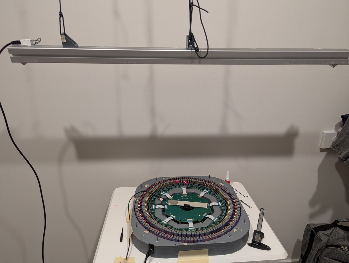
The intersecting LDs reference is hung above the projector, then the mirror is spun up, and the reflection of the lasers onto the device is used to confirm whether the mirror angle is above or below 45 degrees. I used the overhead clothes hanger rod in my closet for this so even more of the apartment is taken up by this project.
During the alignment steps, I could hear occasional pings from dust hitting the spinning mirror even at 12 RPS, which was not something I anticipated. After a few hours of operation, the side of the mirror that was swinging into the air was significantly dustier than the opposite side. With the mirror verified to be at a 45 degree angle, I used the same 4-laser pattern from before, but instead of crossing lines I overlapped individual pixels, which was more precise. After a warm-up time of a few minutes for the mirror and motor to reach a stable temperature, I would align all pixels to a central zenith reference. In this point all LD beams will ideally intersect at a mirror theta angle generated by accurate division in software, so I aligned all LD holders one by one (in groups of four) so they would all overlap at the zenith point. Previously I positioned the projector under a fire sprinkler and used the center of the sprinkler to mark the reference point, however depending on where I stood near the projcetor the floor would be deflected and the projected point on the ceiling would move by more than a pixel spot size, so for the more precise alignment instead of a physical object reference I projected a calibrated pixel to which I aligned all others. This pixel alignment took about an 8 hour work day.
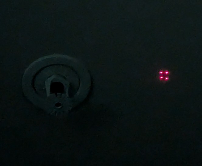
The pixel intersection alignment is similar to the X alignment, but with the lines of the X reduced to dots for higher accuracy. The process is difficult to convey in a photograph as it's just dots on a ceiling, but as an illustration the 4 dots shown here would be overlapped into a single dot by adjusting the corresponding LD holders. When 4 more overlapped dots surround this central one, a correct alignment solution is found.
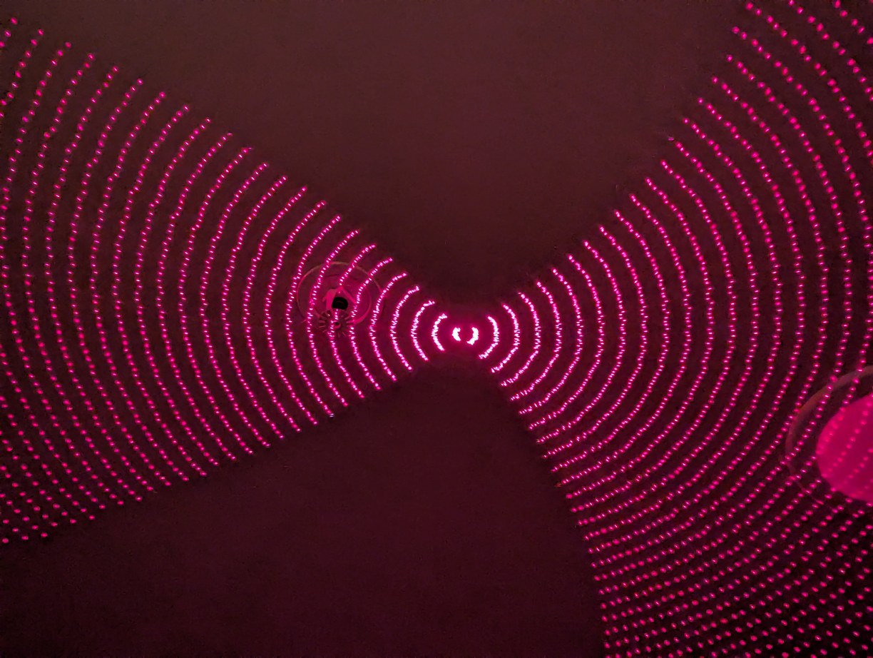

After the dots alignment, the latitude circles are much clearer, and the horizon has a nice square grid.


The same pattern projected in a bigger room shows an overall reasonable performance. Looking closely, it is possible to make out non-idealities, but it is not worth spending more time on alignment given the limited long-term stability of 3D printed parts.
Having the adjustment bolts in front of the laser diode ended up being helpful for alignment - it was necessary to do this in a dark room to see the laser spots clearly, and the laser beam would hit the hex key when it was inserted in the bolt associated with the particular LD that was being aligned, which gave a visual indication that I found the correct bolt. Also by tilting the handle of the hex key back and forth, the laser spot could be made to vary in brightness, so I could tell which spot I should look at as I make the adjustments. Really, the motor should have had kinematic adjustments to allow for changing the axis of rotation, which I vaguely intended to do originally (the motor holder had 3 mounting bolts for this purpose) but then forgot as the project developed. The misalignment between the motor axis of rotation and the average plane of the PCBs had to be handled entirely by the LD holders, which required more adjustments than if I could simply tilt the motor slightly. Further, the mirror holder should also have fine adjustment, which I included in the original design but later thought would not be necessary (I still had this ability with the 3 bolt mount, but it was not as convenient or precise as a flexure mechanism). The projector base was also not easy to clean - there were many pockets and internal corners that could fill up with dust and any objects that happened to fall in (such as a few nuts and washers I dropped before changing the procedure to use a magnet) - and with the alignment steps complete I had no interest in removing the multiple boards that would be necessary to access all the internal regions for cleaning. The lid thus plays an important role not only for protection during transport, but for keeping dust from falling into the projector during storage.
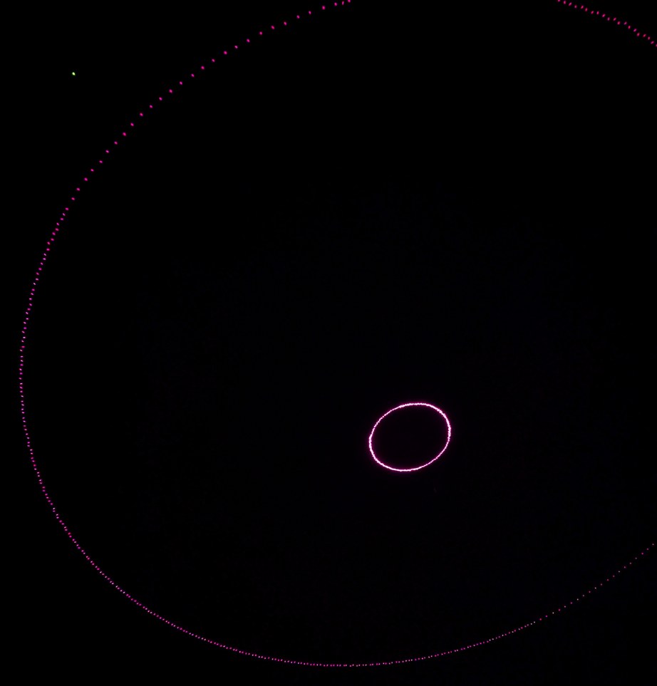
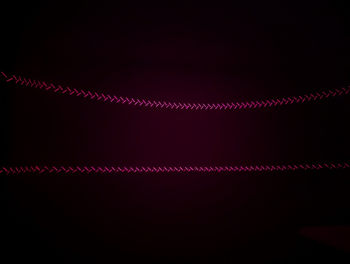
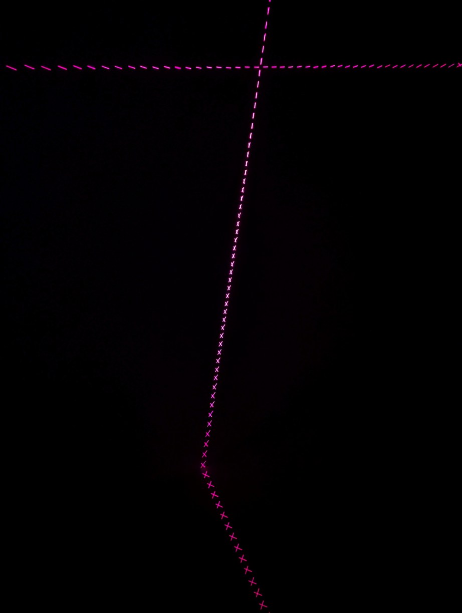
A few more patterns to confirm LD alignment, such as circles which are now more circular than earlier, as well as switching back to the lines of X alignment mode at different phase offsets, creating interesting symmetric images. In the central image, the lower lines are cut off by the top of the projector and represent the lowest projected angle, approximately 2.3 degrees above the horizon.
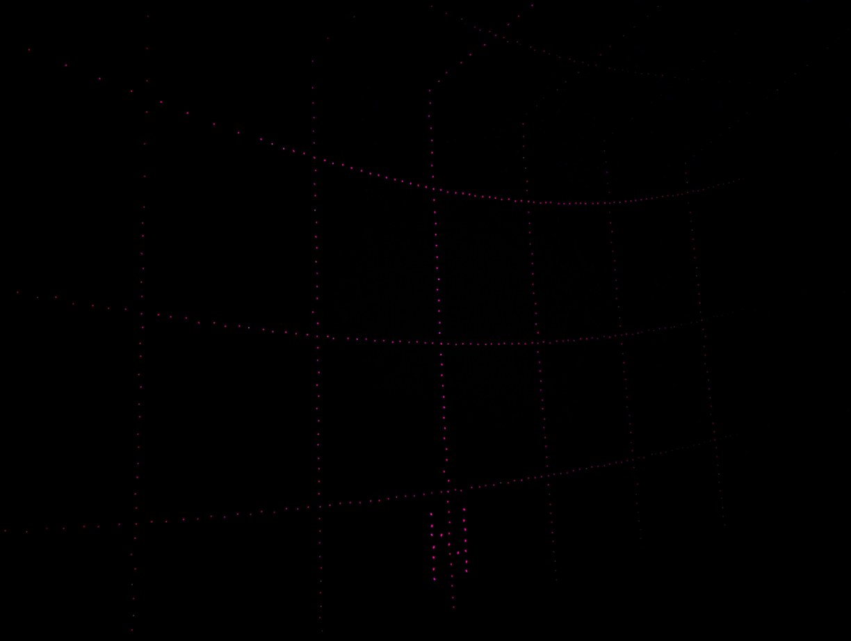
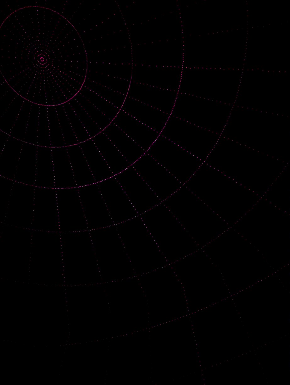
Projection of a latitude and longitude grid pattern, with arcs at every 10 degrees in phi and theta, and letters N,E,S,W marking the different cardinal directions (N is seen in the photo above).
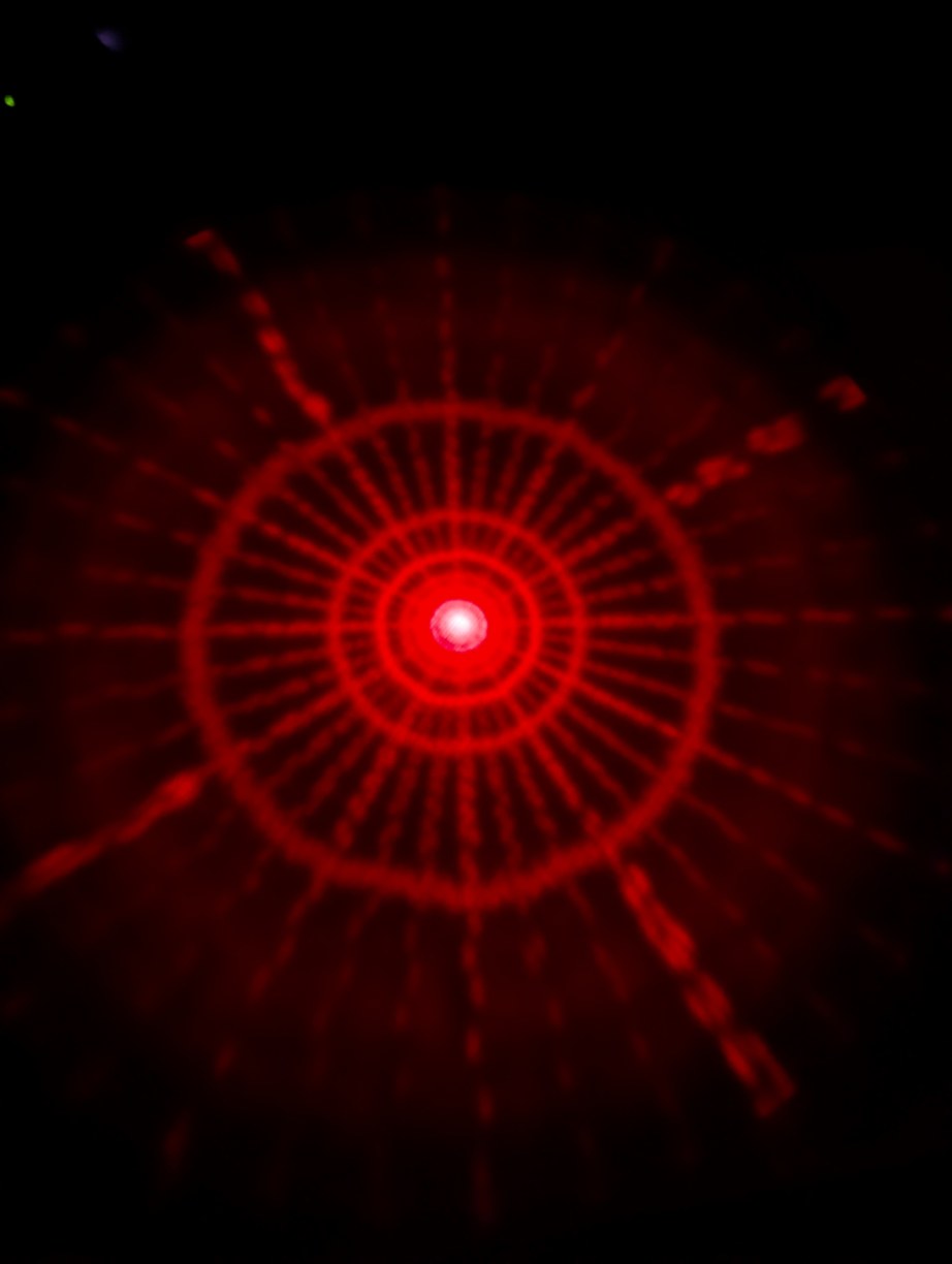
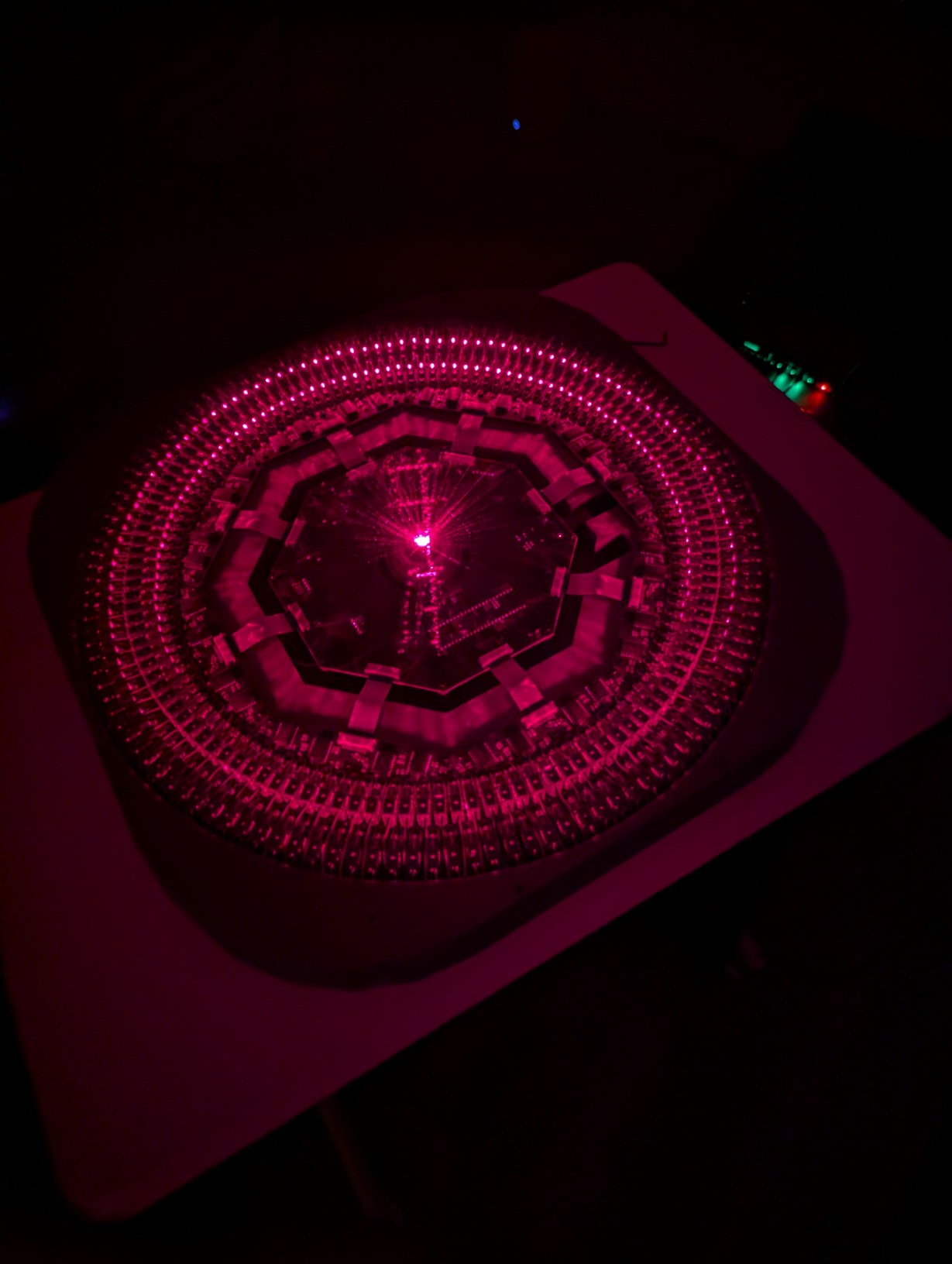
With the same pattern as above, on left, placing the lid (through which the diffused laser beams can be seen) on top of the projector causes the spherical coordinates to be projected onto a plane. On right, without the lid, the laser beams look like they are all emitted from the virtual center point.
With the alignment finished, I tested the projector over multiple days for stability in laser orientation, and it was better than the design specifications (which was a loose target of each pixel staying within 0.5 pixels of its ideal position). Unfortunately during testing I once plugged in the USB cable before the PoE cable, which caused 5 V to be applied to the buffers without 5 V rail power, which seems to have damaged them as they now draw an extra 40 mA of quiescent current (or maybe there is some other issue). It probably would have been better to not isolate the different power rails so this cannot happen, or include some other safety interlock, a lesson for the future. Despite the increased current draw, the projector seemed to be functioning as before, and taking out the main PCB for repairs is very inconvenient once the mirror is installed (as it takes about an hour to re-align the mirror) so I will keep using this PCB while it is still working. On the positive side, there appeared to be no issues due to electro-magnetic interference or current spikes even with all pixels active with 7.5 MHz bit clock (the approximately 2.5 A peak current draw in this case (at duty cycle of 0.1) caused audible high-pitched noise, probably from the ceramic capacitors due to piezoelectric effect; I also attempted to draw full lines instead of pixels, which changes the 2.5 A to a continuous rather than peak current, but this caused the rail voltage to drop low enough that the Teensy reset). The DMA and hardware-based synchronization functioned perfectly, with no jittery or erroneous pixels. To avoid the need to keep plugging in the USB cable (which is tricky as it has to be pushed into the receptacle on the Teensy PCB out of sight under the main PCB and mirror) I wrote some code that would receive a .hex file over ethernet and then write it into flash memory similar to what the bootloader would do, based on the FlasherX code. By this point I had given up on plans to make the server HTTP and HTML compliant, as there was no real benefit to it (the protocol for sending files through HTML forms is convoluted), and instead used a basic binary protocol to exchange pixel and firmware data over TCP with a C# program running on my computer. The server would still return a simple HTML page with a status message if connected with a web browser.
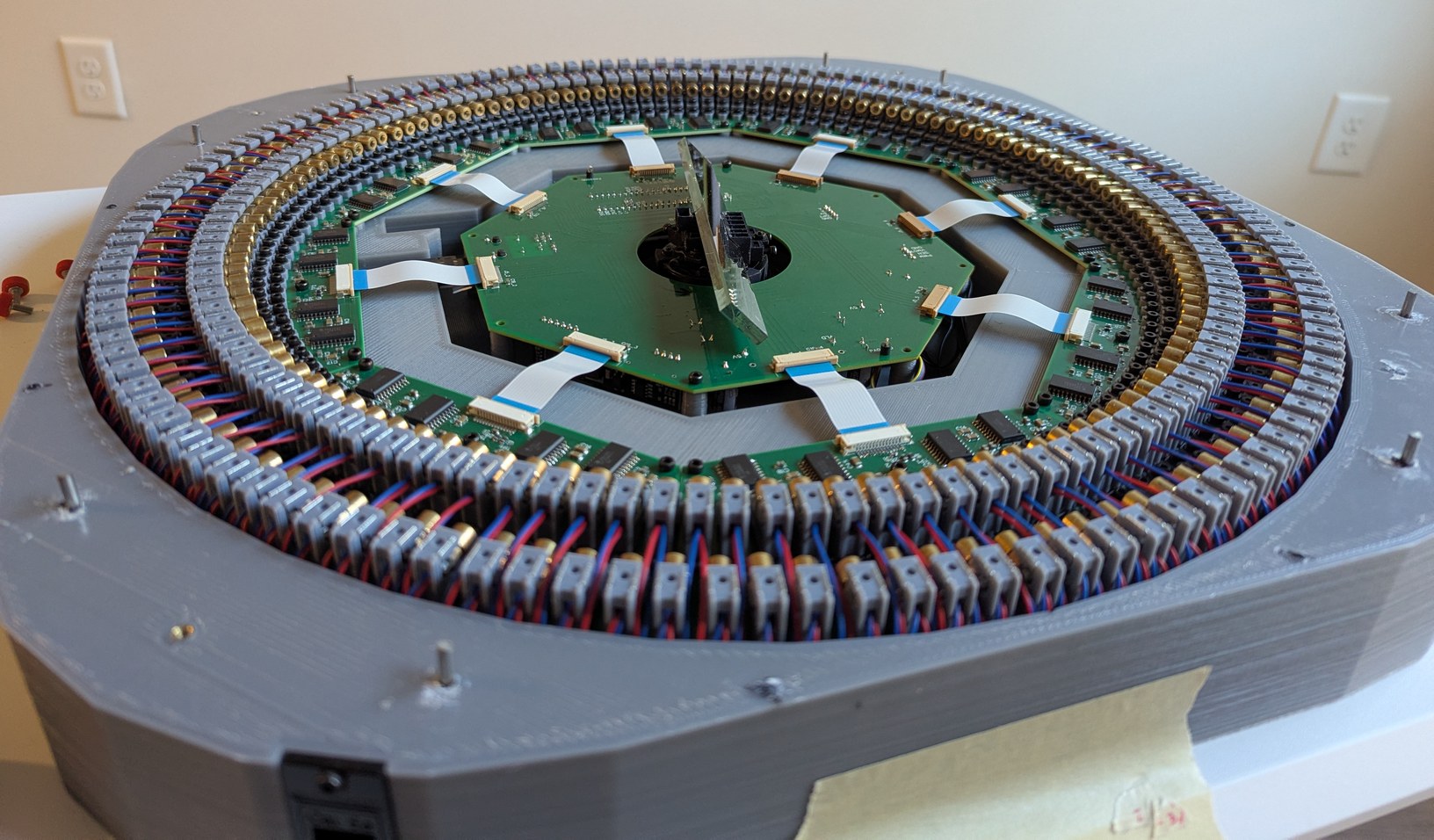
Completed projector with lowered lid protection pins. The outer metal pins mark the lowest angle at which the projector can draw pixels. The top of the projector appears too open, as if there should be another enclosing structure to aid in keeping the LDs aligned or the mirror protected from dust, however this layout is required because the entire hemispherical angle range above the LDs and mirror is used by the projector.
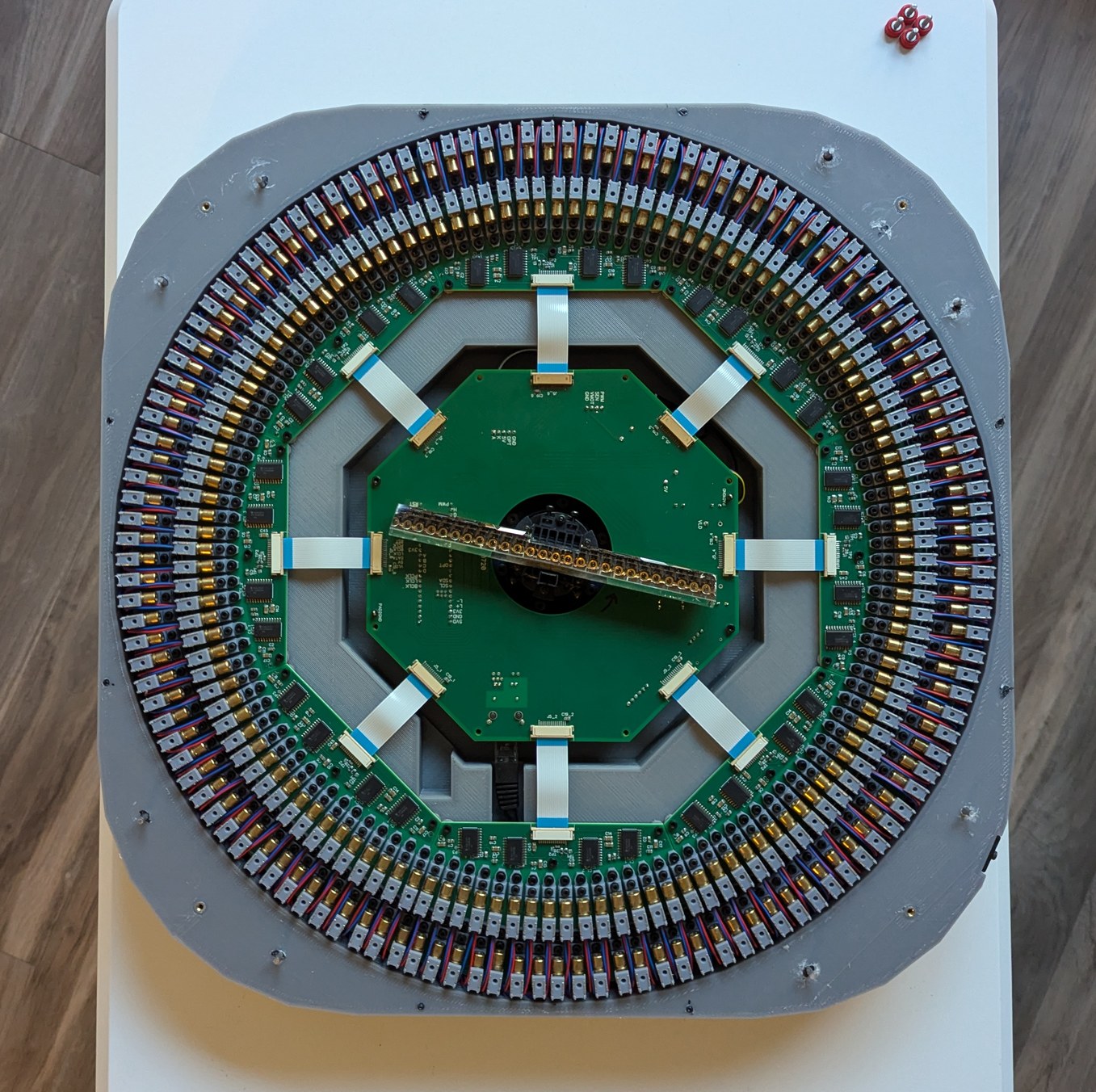
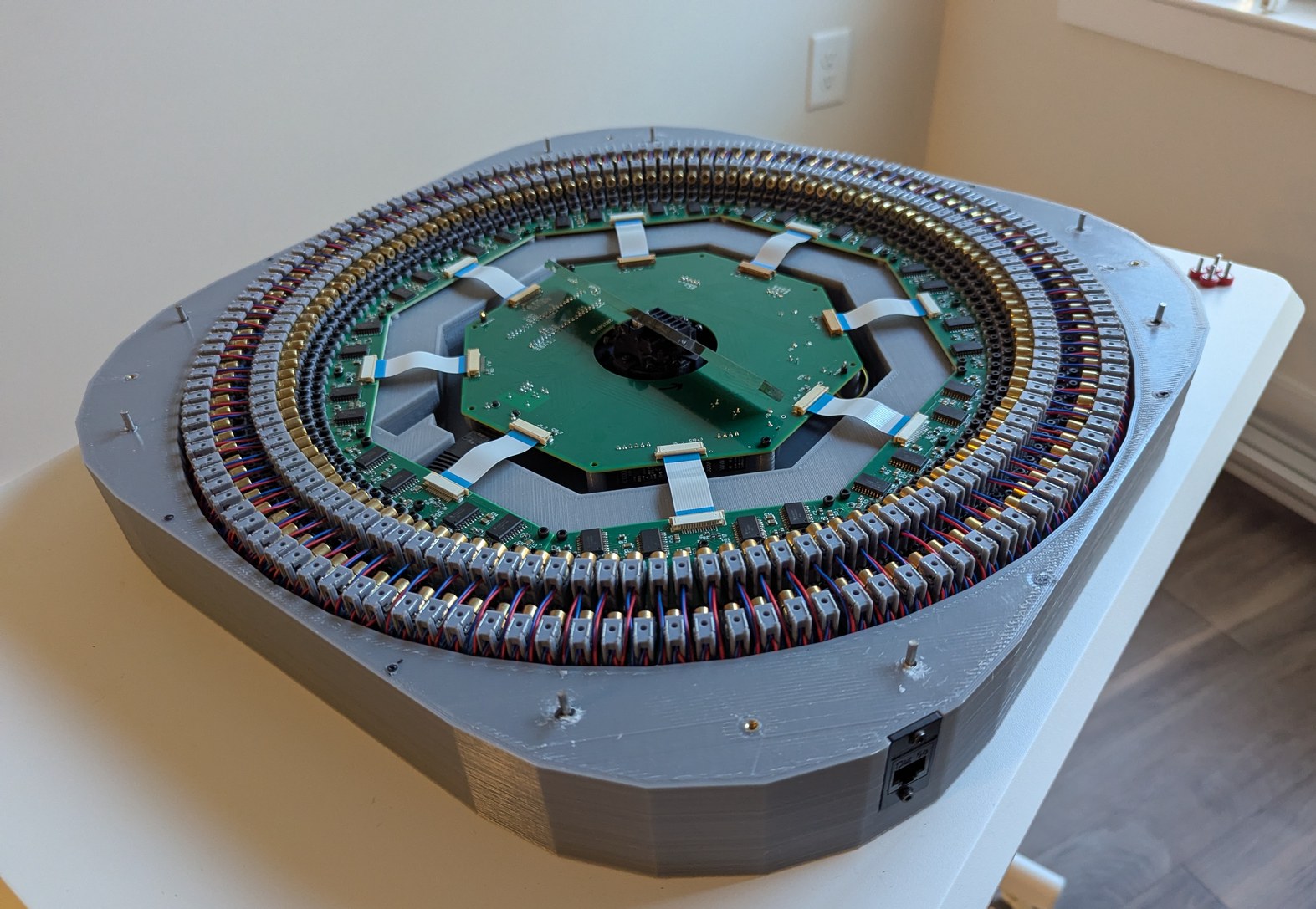
More photos of completed projector. Viewed from the top, it is possible to see the mirrored arc of LDs as if the LDs were in an arc passing under the projector, giving some intuition to how the spinning mirror can project points in a spherical coordinate system.
One problem with this projector design is the use of a theta-phi pixel basis. While this matches the intersection points of latitude and longitude lines one would draw on a globe, this also means that a lot of pixels are concentrated in small circles near the "pole" overhead. The distinction between pixels is unimportant in those circles because the circles are so small, and yet the resolution budget used up by them is the same as by the circles near the horizon where distinction between pixels is important. Visually it feels like the resolution could be improved by a factor of two if the pixels near the zenith could be somehow spread out towards the horizon. A fish-eye lens would be a better choice in this sense, because it maps the center of an image (small circumference) to small circles and the outside of an image (large circumference) to large circles.
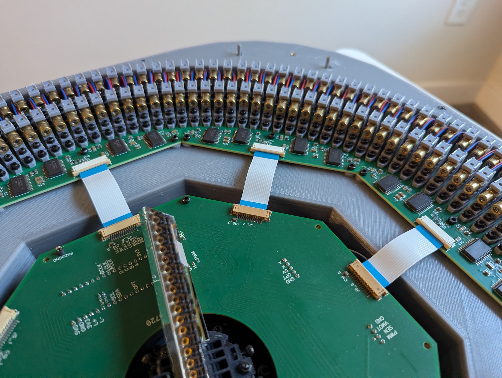
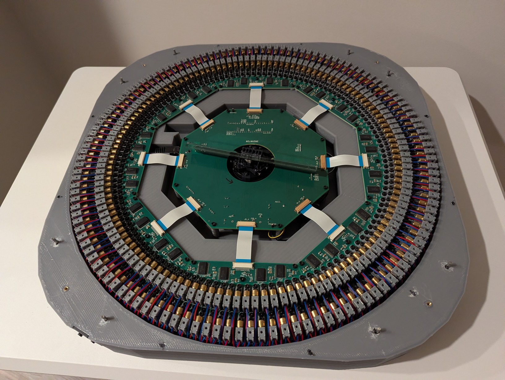
More photos of completed projector. Looking closely, the LD holders do not appear uniformly spaced. However this is due to misalignment between the LD die inside each cylindrical package and the central axis of the cylinder. With the beams aligned to be uniformly spaced, the cylinders look misaligned (handling this was a major function of the LD holders).
Implementing communication over ethernet and finishing up the stellar map software, I was able to display star positions on the projector for the first time. (Partially finished C# code here, which uses star information from V/53A, constellation descriptors from Stellarium, and solar system calculations from Paul Schlyter's website (possibly based on Jean Meeus' Astronomical Algorithms book).) The image looked good, however the brightness levels were difficult to distinguish. Originally I used steps of (5, 11, 16) us defined using the reset line of the shift registers, which I thought would give adequate contrast but it did not. I think part of the issue is that as the duration gets longer, the laser beam spot is scanned and it does not appear brighter, only more spread out in a line. I changed the FlexIO configuration to use the output enable line of the shift registers, which allows pulses to be shorter than the 5 us data shift period; then the steps were (2.3, 9.7, 12) us. Now I could see a reasonable contrast between the 2.3 us and 12 us pulses, though the 9.7 us was barely distinguishable from 12 us. I realized that a high contrast ratio and dynamic range could be a great strength of this projector, so I changed the FlexIO configuration to use both the output enable and reset lines, with 3 data shifts per pixel instead of 2, to generate steps of (0.33, 2, 14) us. These are separated in light output by factors of 6 and 7, for a dynamic range of 42 which is about half of the range in star magnitude between 0 and 5 (with 5 being considered at the limit of unaided vision, and what is covered in the V/53A "Catalogue of the Brightest Stars" that I am using to generate the star map), which I think is a reasonable compromise so that the contrast spread is not excessive (the FlexIO module is capable of generating the full factor of 100 range, but then the 3 brightness levels would look jarringly different with no intermediate steps). With the ability to output these logarithmic steps, the projector output is quite impressive, and I feel justified for taking the extra effort to implement different brightness levels. In fact I wish there were some way to add more brightness steps, such as 31 instead of 3, as that would greatly improve the realism of the rendered scene which is important for identifying constellations (brightness gives cues as to which stars to focus on, and with only 3 brightness levels many stars are not as easy to single out as in the real night sky, increasing reliance on purely size and pattern based recognition). There is no clear way to achieve this with the hardware I am using, but if I were starting over, this feature would be something to put more focus on (the required timing is in principle achievable with a modified LD driving scheme). I found that to achive the proper visual effect, it is important that the brightness steps be logarithmic rather than linear, and I feel like the dynamic range and contrast of this projector design is unique compared to other planetarium projectors I have seen, giving a visual experience of bright and dim stars separated by black space that is truly reminiscent of the night sky. Trying the same with a regular LCD projector is unsatisfyingly bland: bright and dim stars look similar and the space between them looks like a gray haze. The red color of the laser preferentially activates the rods of the eye, akin to what would happen when viewing stars at night, and slight timing jitter in mirror synchronization causes the laser dots to wander a bit causing a twinkle effect somewhat similar to starlight and atmospheric refraction, making the visualization slightly more realistic in an unintended way.


Projected section of a star map, with a long exposure photograph that makes the colors look more dramatic than by eye. The constellation near the center is Cygnus, coarsely outlined in red in the second photo.
From initial testing with a single laser diode and a square wave generator, I found that at least 30 Hz refresh rate would be necessary and a 2 us long flash would be the minimum perceivable duration. I'm not sure why the results with the projector have given different numbers, probably in parts because it is easier to make out an entire scene rather than one dot, because I use the projector in a darker room than when I did the initial test, and because the projector LD driver is much better suited to outputting strong driving waveforms compared to the square wave generator. With the projector, I have determined that a 12 Hz refresh rate is reasonable (flickering is perceivable but not too distracting) and pulses as short as fractions of a microsecond are visible (in a very dark room).
Another aspect of using this projector is, of course, the very wide field of view. Habitually I look towards a wall of the room to view the scene, like one would with a regular video projector, then I have to remind myself that there is a whole another half of the scene that is happening behind me! This gave good training in being aware of the full surroundings when observing the virtual sky, and how to mentally combine the different images while turning my head to cover the projected region, which was one of the goals in building this project. The image is most accurate when viewed with one's head close to the projector, but in that case it is likely that one may look into a laser beam coming from the projector. At the laser duty cycles involved here, this occurrence is slightly uncomfortable but should not involve any risk of ocular injury (this is a benefit of using 256 low power lasers instead of 1 high power laser).
With this successful result, I brought the HTTP server to a more complete state, allowing changing alignment, and filter (and possibly timer) parameters and writing them to EEPROM, as well as displaying a detailed status report. Another minor change was turning off the projector's ethernet status LED during operation, to further improve the background light level when using the projector in a dark room. Because the 0.33 us dots were too dim for viewing in a typical room, I added two higher brightness modes of (2, 4.8, 14) us and (2, 6.8, 20.8) us achieved by fixing the reset line, of which the latter appeared more useful due to higher dynamic range. After some trial and error (mostly in taking out optimizations I thought would make the flash writing code faster but instead caused memory corruption, until the code looked almost identical to the FlasherX code), the firmware update over ethernet was also functional, so I could finally unplug the USB cable which made it difficult to fully close the lid. I lowered the lid protection pins so they would not interfere with the lowest row of pixels near the horizon, and while doing so realized that this function probably could have been better served by using threaded rod and wing nuts in the existing M3 threaded inserts, rather than melting and drilling a bunch of holes into the base and lid, but the pins worked as intended. With the new web interface, I attempted momentarily (to avoid overheating) increasing the motor speed to 18 RPS, and the flickering effect improved substantially, giving a more solid visual experience. Nonetheless there is some charm in the flicker at 12 RPS, as it looks in a sense similar to atmospheric refraction, so there is a greater feeling of looking at distant objects; also at 12 RPS the spinning mirror is almost silent whereas at 18 RPS it sounds like it's about to take flight. Due to the thermal, noise, and dust concerns, I intend to keep operating this in a low speed regime.
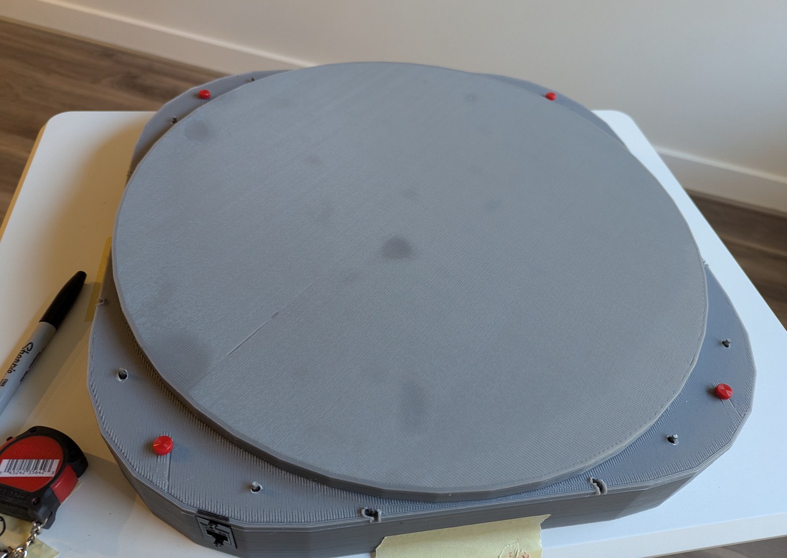
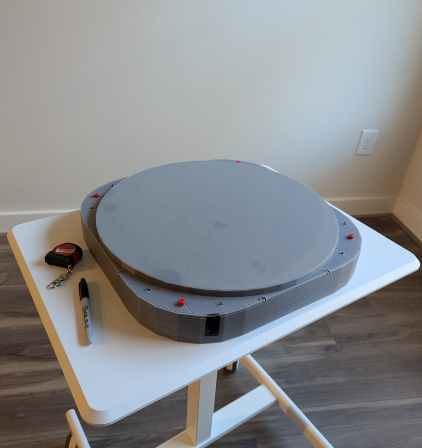
Completed projector with the lid installed. This was more work than it should have been, due to having to match all the pin locations and having to cut the bolts to the proper length as I could not readily find shorter ones to purchase.
With the lid installed, I could transport this project to different locations for demonstration. Over weeks some LDs moved slightly out of alignment, but this is largely inconsequential for viewing star maps (it would be quite noticeable for viewing bitmap graphics). Initially I planned to use hot glue to secure all LDs after alignment, but I became worried about the risk of the glue somehow making things worse and then being unable to adjust anything without taking apart all the boards; instead I decided to leave everything unglued so that individual LDs that drift out of alignment can be adjusted back with ease. Overall this project has been a marathon - some of the first sketches are from August 2024, and it seems that each part has required multiple iterations - but I am happy to say that the project has met all the original design goals. It is indeed possible, with great patience, to align 256 laser diodes held in 3D printed resin parts, and to synchronize them to a spinning mirror with better than 0.1 degree resolution.